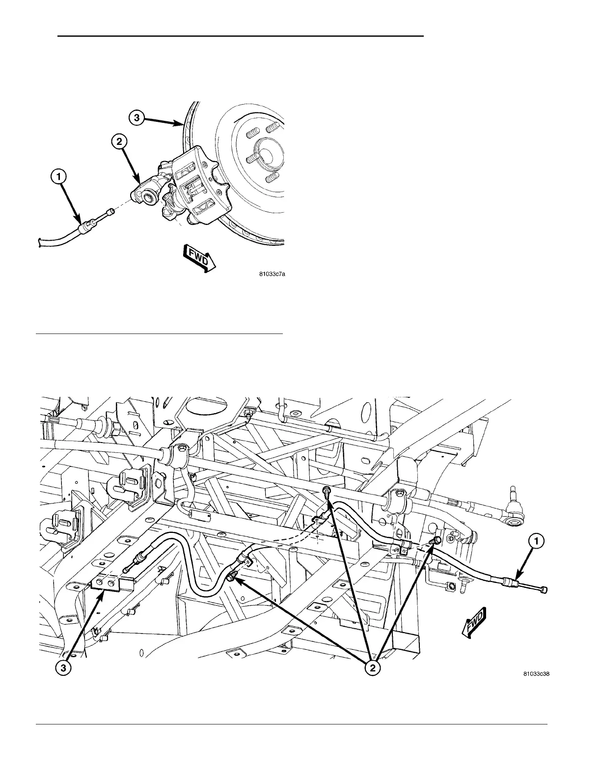
(12) Remove cable end from apply lever on caliper
(Fig. 61).
(13) Remove cable from caliper bracket holding
cable housing (Fig. 61).
(14) Remove screws from three cable routing
clamps (Fig. 62).
(15) Remove cable.
INSTALLATION
(1) Install cable through framework as shown (Fig.
62).
(2) Insert lever end of cable through interior access
hole in tunnel area (Fig. 62). Slide cable housing into
hole until retainer snaps into place in body.
(3) Position three cable routing clamps and install
screws (Fig. 62). Tighten screws to 10 N·m (90 in.
lbs.) torque.
(4) Insert parking brake caliper end of cable
through caliper bracket and slide cable housing into
caliper bracket (Fig. 61).
(5) Install cable end into apply lever on caliper
(Fig. 61).
(6) Grasp parking brake cable between cable hous-
ing and apply lever and pull outward until enough
slack is present to install cable onto pivot wheel.
Once on wheel, push any extra cable back into cable
housing.
(7) Clip ABS wheel speed sensor to parking brake
cable.
Fig. 62 Cable Routing - Right Shown (Left - Typical)
1 - PARKING BRAKE CABLE
2 - ROUTING CLAMP SCREWS
3 - INTERIOR ACCESS HOSES IN BODY
Fig. 61 Cable At Parking Brake Caliper
1 - PARKING BRAKE CABLE
2 - CALIPER BRACKET
3 - BRAKE ROTOR
ZB BRAKES - BASE 5 - 39
CABLE - PARKING BRAKE (Continued)










 To Next Page