ENGINE COOLANT
TEMPERATURE SENSOR
DESCRIPTION
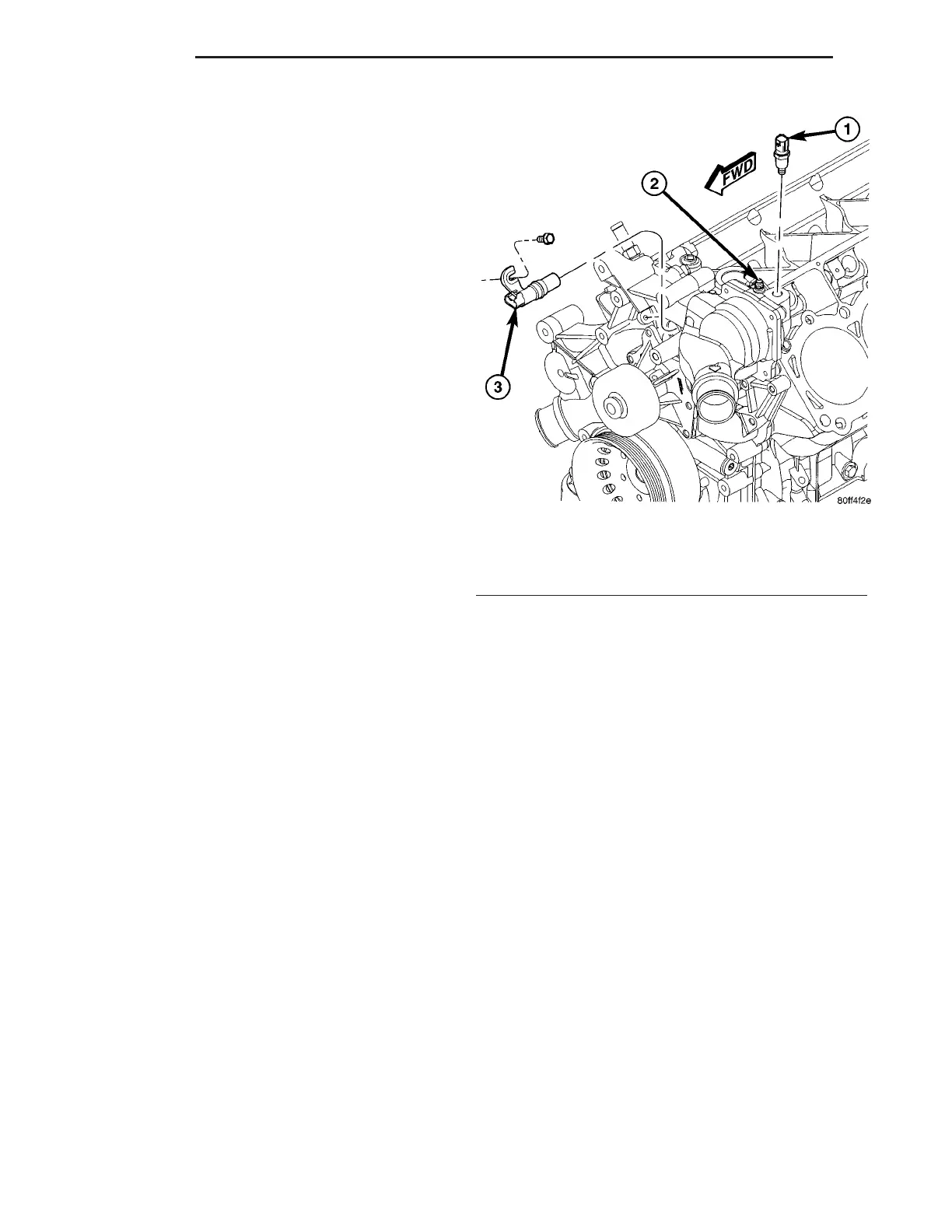
The engine coolant temperature sensor threads
into the timing chain cover at the left front side of
the engine (Fig. 13).
OPERATION
The PCM determines engine coolant temperature
from the engine coolant temperature (ECT) sensor.
The ECT sensor is a two wire Negative Temperature
Coefficient (NTC) sensor. As temperature increases,
resistance in the sensor decreases. The PCM sends 5
volts to the sensor and is grounded through the sen-
sor return line. As coolant temperature varies, the
coolant temperature sensor resistance changes
resulting in a different voltage value at the PCM
engine coolant sense circuit.
Until the engine reaches operating temperature,
the PCM demands slightly richer air-fuel mixtures
and higher idle speeds.
This sensor is also used for cooling fan control, A/C
cutoff at high coolant temperatures, and temperature
gauge operation.
REMOVAL
(1) Partially drain the cooling system.
(2) Disconnect the electrical connector from the
engine coolant temperature sensor.
(3) Remove the sensor (Fig. 13).
INSTALLATION
(1) Install sensor (Fig. 13). Tighten to 27 N·m (20
ft. lbs.) torque.
(2) Connect electrical connector to sensor.
(3) Fill cooling system
ENGINE COOLANT
THERMOSTAT
DESCRIPTION
The engine coolant thermostat and housing is
located at the front of the engine, mounted to the
timing chain cover (Fig. 14). The thermostat is a
moveable sleeve type.
OPERATION
The thermostat’s primary purpose is to maintain
engine temperature in a range that will provide sat-
isfactory engine performance and emission levels
under all expected driving conditions.
The thermostat is unique because the center does
not open and close like a conventional thermostat; it
works like a sliding sleeve. The outside sleeve moves,
directing coolant flow through the engine block or
through the bypass passages back to the water
pump. During warm-up below 85°C (185°F), the ther-
mostat is seated in the retracted position. This will
allow the coolant to flow into the bypass passage,
and back to the water pump. At 85°C (185°F) the
thermostat begins to open, allowing coolant to flow
through both the bypass and the radiator. At 104°C
(219°F) the thermostat will fully open, blocking the
path to the bypass, allowing all coolant to flow
through the radiator.
DIAGNOSIS AND TESTING - THERMOSTAT
The “open too soon/stuck open” type failure mode is
included in the on-board diagnostics. The check
engine light will not be lit by this condition. If ther-
mostat has failed open, a Diagnostic Trouble Code
(DTC) will be set (P0125/P1281). Do not change a
thermostat for lack of heat by gauge or heater per-
formance, unless a DTC is present, (Refer to 7 -
COOLING/ENGINE - DIAGNOSIS AND TESTING)
for other probable causes. Failing shut is the most
common mode of failure, and normally, only on high
mileage vehicles. The temperature gauge will indi-
cate a failed closed failure.
Fig. 13 Engine Coolant Temperature (ECT) Sensor
1 - ENGINE COOLANT TEMPERATURE (ECT) SENSOR
2 - COOLING SYSTEM BLEED SCREW
3 - CAMSHAFT POSITION SENSOR
7 - 18 ENGINE ZB















 To Next Page