For hydraulic fluid routing information refer to
(Fig. 20).
CAUTION: Do not attempt to service the hydraulic
cooling fan or fan drive separately. Replace the
cooling fan as an assembly. Failure to do so may
cause severe damage to the hydraulic cooling fan
assembly.
OPERATION
HYDRAULIC FAN STRATEGY
The hydraulic cooling fan is controlled by the PCM.
A PWM (Pulse With Modulated) signal from the PCM
controls the fan from 0 to 100% of the available fan
speed. There are two inputs to the PCM that deter-
mine what speed percentage of fan is required by the
vehicle. These inputs are:
• Engine Coolant Temperature
• A/C System Pressure
By monitoring these two parameters, the PCM can
determine if cooling airflow is required. If airflow is
required, the PCM will slowly ramp up (speed up)
the fan speed until the parameter(s) are under con-
trol. Once the temperature or pressure is reduced to
within operating parameters the fan will ramp up,
ramp down, or hold its speed to maintain the temper-
ature / pressure requirements.
NOTE: Even if the PCM is not requesting fan on
operation the fan blade will usually spin between
100 and 500 RPM when the vehicle is at idle. This is
due to a controlled minimum oil flow requirement
through the fan drive motor.
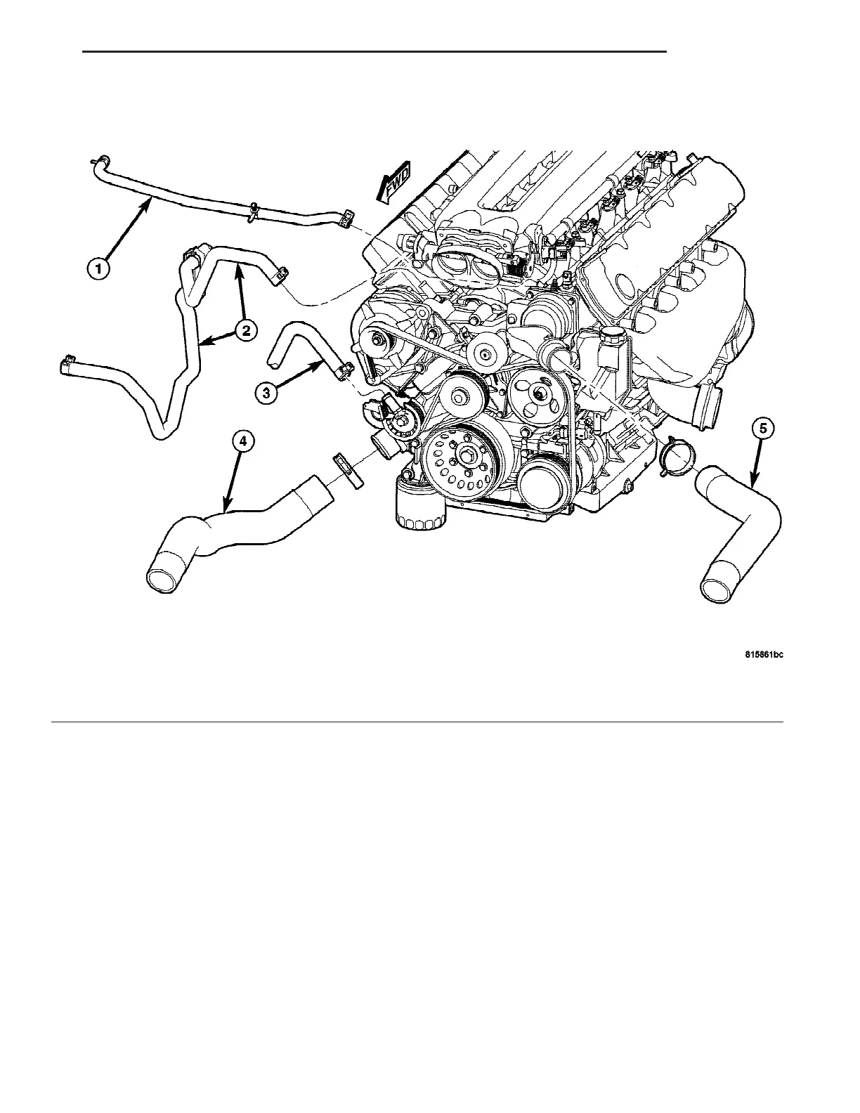
Fig. 19 Cooling System Hoses
1 - COOLANT BOTTLE INLET HOSE
2 - HEATER SUPPLY AND RETURN HOSE ASSY.
3 - OIL COOLER RETURN HOSE
4 - LOWER RADIATOR HOSE
5 - UPPER RADIATOR HOSE
ZB ENGINE 7 - 21
RADIATOR FAN (Continued)















 To Next Page