REMOVAL
(1) Make sure ignition switch is in OFF position
and all accessories are turned OFF.
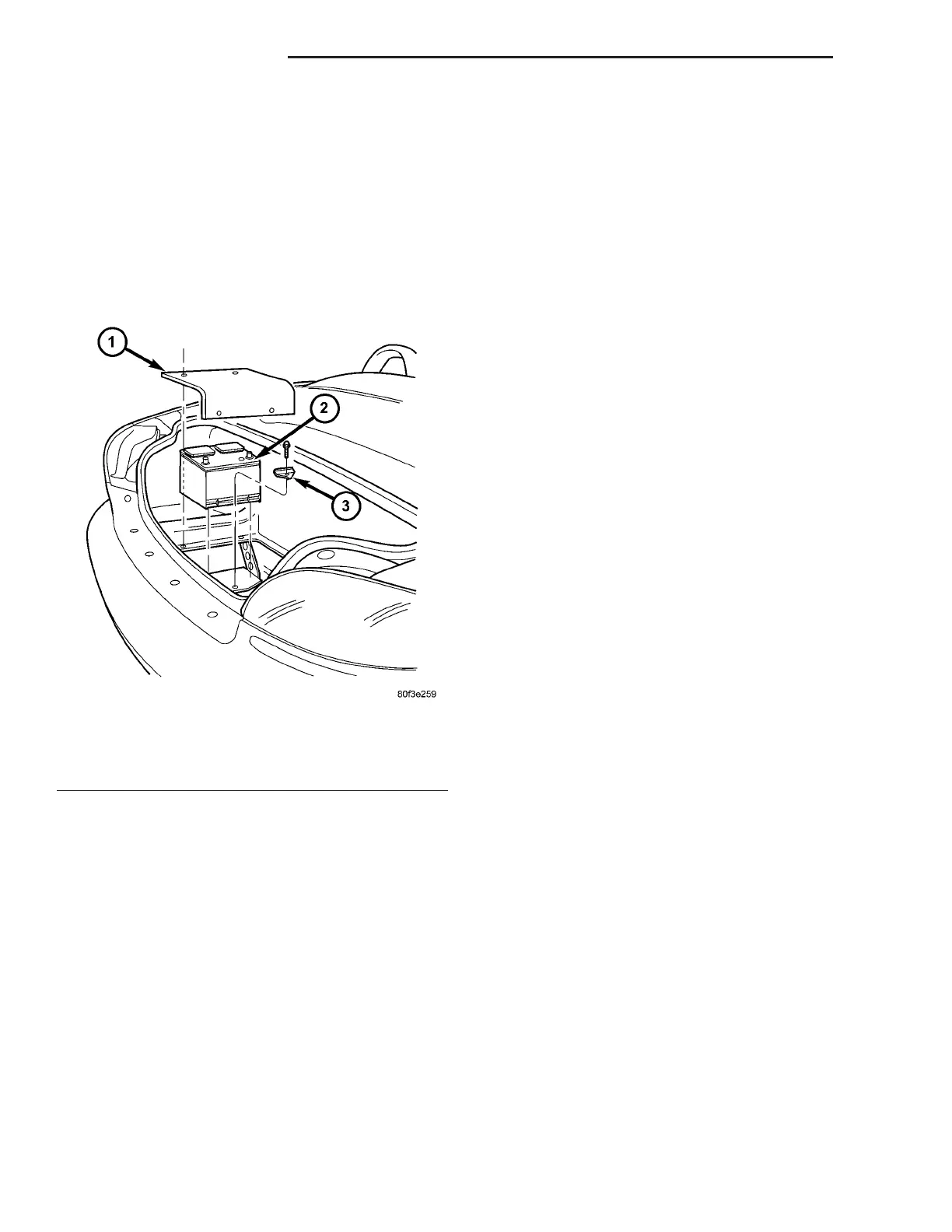
(2) The battery is located in the trunk.
(3) Remove the screws attaching the battery cover
and remove the cover.
(4) Disconnect the battery cables from the battery
terminals. Remove the battery negative cable first
(5) Remove the battery hold down clamp (Fig. 6)
and remove the battery from the vehicle.
INSTALLATION
(1) Position the battery in the battery tray.
(2) Install the battery hold down clamp and bolt.
Torque the bolt to 9 N·m (80 in. lbs.).
(3) Connect the battery POSITIVE cable.
(4) Connect the battery NEGATIVE cable.
(5) Install the battery cover.
BATTERY HOLDDOWN
REMOVAL
(1) Remove the screws attaching the battery cover
and remove the cover.
(2) Disconnect and isolate the negative battery
cable.
(3) Remove the single battery hold down retaining
fastener.
(4) Remove the battery hold down from the vehi-
cle.
INSTALLATION
(1) Install the battery hold down in the vehicle.
(2) Install the single battery hold down retaining
fastener. Torque the bolt to 9 N·m (80 in. lbs.).
(3) Connect the negative battery cable.
(4) Install the battery cover.
BATTERY CABLES
DESCRIPTION
The battery cables are large gauge, stranded cop-
per wires sheathed within a heavy plastic or syn-
thetic rubber insulating jacket. The wire used in the
battery cables combines excellent flexibility and reli-
ability with high electrical current carrying capacity.
The battery cables feature a top post battery termi-
nal made of stamped sheet metal that is stamped
onto one end of the battery cable wire. Large eyelet
type terminals are crimped onto the opposite end of
the battery cable wire and then solder-dipped. The
battery positive cable wires have a red insulating
jacket to provide visual identification of the battery
positive terminal. The battery negative cable wires
have a black insulating jacket to provide visual iden-
tification of the battery negative terminal.
The battery cables cannot be repaired and, if dam-
aged or faulty they must be replaced. Both the bat-
tery positive and negative cables are available for
service replacement only as a unit with the battery
wire harness, which may include portions of the wir-
ing circuits for the generator and other components
on some models. Refer to the appropriate wiring
information in this service manual for the location of
the proper battery cable wire harness diagrams. The
wiring information also includes proper wire and con-
nector repair procedures, further details on wire har-
ness routing and retention, as well as pin-out and
location views for the various wire harness connec-
tors, splices and grounds.
OPERATION
The battery cables connect the battery terminals to
the vehicle electrical system. These cables also pro-
vide a path back to the battery for electrical current
generated by the charging system for restoring the
voltage potential of the battery. The battery termi-
nals on the ends of the battery cable wires provide a
strong and reliable connection of the battery cable to
the battery terminals. The eyelet terminals secured
to the opposite ends of the battery cable wires pro-
vide secure and reliable connection of the battery
cables to the vehicle electrical system.
Fig. 6 BATTERY LOCATION
1 - BATTERY COVER
2 - BATTERY
3 - HOLDDOWN BRACKET
8F - 12 BATTERY SYSTEM ZB
BATTERY (Continued)















 To Next Page