neatly (Fig. 7). Extend the epoxy application onto the
grid line or the bus bar on each side of the break.
(2) Follow the instructions in the repair kit for
preparing the damaged area.
(3) Remove the package separator clamp and mix
the two conductive epoxy components thoroughly
within the packaging. Fold the package in half and
cut the center corner to dispense the epoxy.
(4) Apply the epoxy through the slit in the mask-
ing tape or template. Overlap both ends of the break
by at least 19 millimeters (0.75 inch).
(5)
Carefully remove the masking tape or template.
CAUTION: Do not allow the glass surface to exceed
204° C (400° F) when using a heat gun, or the glass
may fracture.
(6) Allow the epoxy to cure 24 hours at room tem-
perature, or carefully use a heat gun for fifteen min-
utes. When using a heat gun, hold it approximately
25.4 centimeters (10 inches) from the repair and do
not allow the glass surface to exceed 204° C (400° F).
(7) After the conductive epoxy is properly cured,
check the operation of the rear window defogger
glass heating grid.
REAR WINDOW DEFOGGER TERMINAL REPAIR
CAUTION: Do not use a flame type solder gun or an
electric solder gun rated greater than 500 watts or
damage to the glass may occur.
If the rear window defogger grid terminal(s) is
damaged or separated from the rear window, the new
grid terminal(s) must be securely fastened to the rear
window defogger bus bar by soldering.
(1) If the grid terminal(s) is broken and a portion
of the terminal is still attached to the heating grid,
remove the portion of the clip remaining in the wire
harness connector(s).
CAUTION: To prevent the glass from fracturing, do not
allow the glass surface to exceed 204° C (400° F).
(2) If the grid terminal(s) is broken and a portion
of the terminal is still attached to the rear window
defogger bus bar, apply heat with a solder gun to the
portion of the terminal on the glass until the solder
starts to flow. Remove the terminal and carefully
smooth the solder on the bus bar.
NOTE: Wait five minutes for the glass to cool after
applying heat with a solder gun before proceeding.
NOTE: Use care when cleaning the mating surfaces.
Excessive abrasion may wear away the copper grid
surface causing grid continuity to be lost.
(3) Clean the mating surfaces on the grid bus bar
and the new terminal(s) with “000” Extra Fine Steel
Wool or an equivalent.
NOTE: The terminal attaching clip(s) must face out-
board. Failure to reorient the terminal(s) may result
in an additional failure.
(4) Properly orient the new terminal(s) with the
attaching clip facing outboard in the original loca-
tion(s) on the grid bus bar and hold the terminal(s)
with a metal pick or other suitable pointed tool.
CAUTION: Do not allow the glass surface to exceed
204° C (400° F), glass may fracture.
NOTE: New rear window defogger terminals are pre-
soldered and fluxed. Do not reuse a terminal if it
has been previously heated.
Place the solder gun onto the new terminal(s) and
heat the terminal until the solder flows. Remove the
solder gun and continue to hold the terminal in the
correct position for an additional five seconds.
(5) Allow the solder to cool for ten minutes.
NOTE: To ensure proper installation, do not attach
the wire harness connector(s) to the terminal(s)
until the solder is completely cooled.
(6) After the solder has cooled, reconnect the wire
harness connector(s) and verify operation of the rear
window defogger.
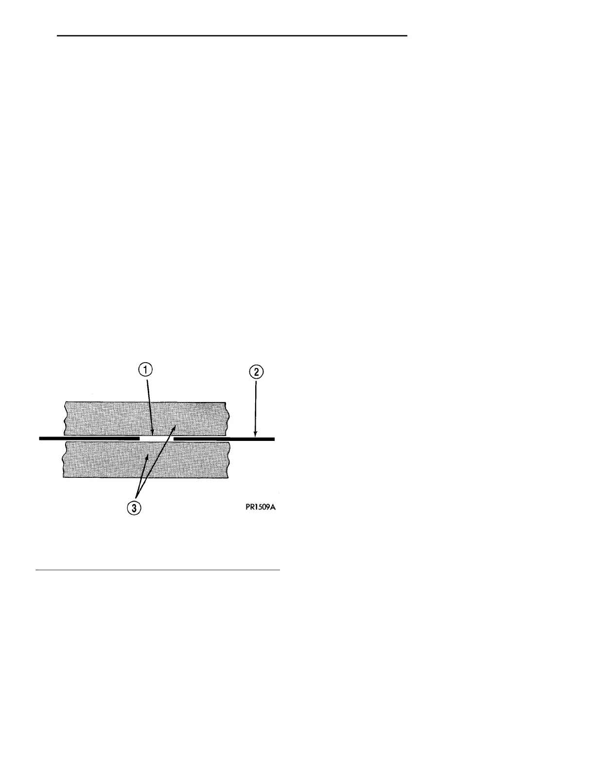
Fig. 7 Grid Line Repair
1 - BREAK
2 - GRID LINE
3 - MASKING TAPE
ZB HEATED SYSTEMS 8G - 5
REAR WINDOW DEFOGGER GRID (Continued)