to 8 - ELECTRICAL/WIPERS/WASHERS/WIPER/
WASHER SWITCH - INSTALLATION).
(2) Install the multi-function switch mounting
screws. Tighten multi-function switch to column
retaining screws to 3 N·m (27 in. lbs.) torque.
(3) Connect both posi-lock harness connectors at
the rear of the multi-function switch.
(4) Instal both upper and lower steering column
shrouds.
(5) Connect the battery negative cable.
(6) Place battery access cover into place and install
four bolts.
(7) Close deck lid.
(8) Verify vehicle and system operation.
FRONT SIDE MARKER LAMP
REMOVAL
(1) Open deck lid.
(2) Remove four bolts to battery compartment
cover and remove cover.
(3) Disconnect and isolate the battery negative
cable.
(4) Remove front fender extension splash shield on
the respective side by removing the fasteners (Fig.
14).
(5) Remove the front side marker lamp by turning
1/4 turn counterclockwise and pulling straight out.
(6) Pull the lamp straight out of the lamp socket
and remove from vehicle.
INSTALLATION
(1) Place marker lamp into socket and install in
rear of headlamp unit. turn 1/4 turn clockwise until
stops.
(2) Install the front fender extension splash shield
on the respective side by and the fasteners (Fig. 14).
(3) Connect the battery negative cable.
(4) Place battery access cover into place and install
four bolts.
(5) Close deck lid.
(6) Verify vehicle and system operation.
REAR SIDE MARKER LAMP
REMOVAL
It is not necessary to remove the tail lamp unit to
change lamps.
(1) Open deck lid.
(2) Remove four bolts to battery compartment
cover and remove cover.
(3) Disconnect and isolate the battery negative
cable.
(4) Remove the two Torx head retaining screws to
the access panel of the respective side of the vehicle
and remove panel.
(5) Reach in behind the tail lamp unit and turn
the respective bulb counterclockwise, pull forward
and remove.
INSTALLATION
It is not necessary to remove the tail lamp unit to
change lamps.
(1) Reach in behind the tail lamp unit and place
lamp in socket, put in lamp unit opening and turn
the lamp socket clockwise until it locks into place.
(2) Install the two Torx head retaining screws to
the access panel of the respective side of the vehicle.
(3) Connect the battery negative cable.
(4) Place battery access cover into place and install
four bolts.
(5) Close deck lid.
(6) Verify vehicle and system operation.
REPEATER LAMP - EXPORT
REMOVAL
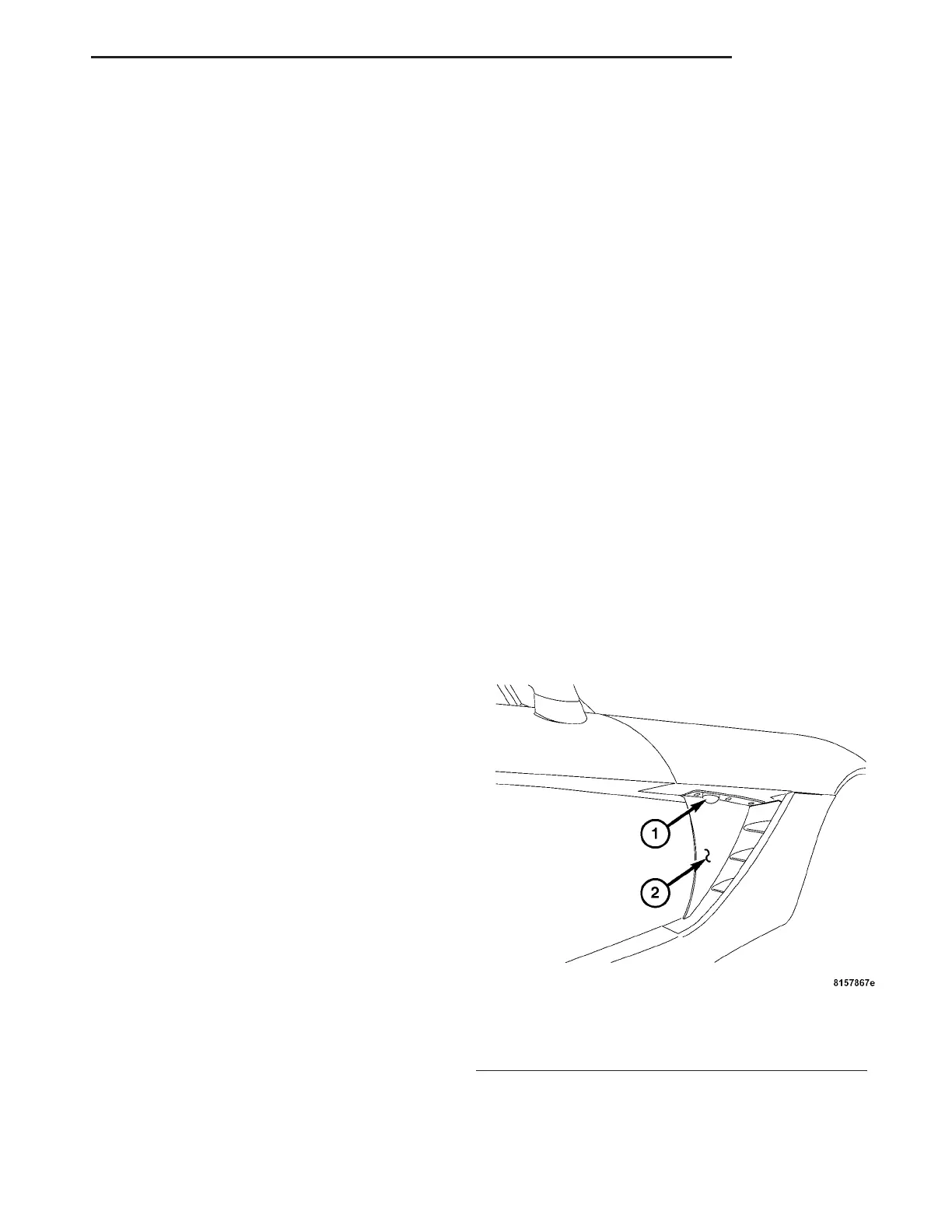
(1) Open the door and reach through the door jam,
depress the side repeater lamp retaining tabs and
release from the hinge cover (Fig. 27).
(2) Pull side repeater lamp out and disengage bulb
socket from lamp.
(3) Rotate and pull the bulb from the socket.
Fig. 27 SIDE REPEATER LAMP
1 - SIDE REPEATER LAMP
2 - HINGE COVER
ZB LAMPS 8L - 31
MULTI-FUNCTION SWITCH - EXPORT (Continued)
 Loading...


