POWER MIRRORS
TABLE OF CONTENTS
page page
POWER MIRRORS
DESCRIPTION ..........................7
OPERATION ............................7
DIAGNOSIS AND TESTING - POWER
MIRRORS ............................7
POWER MIRROR SWITCH
DIAGNOSIS AND TESTING - POWER MIRROR
SWITCH .............................7
REMOVAL .............................8
INSTALLATION ..........................8
SIDEVIEW MIRROR
DESCRIPTION ..........................8
OPERATION ............................8
POWER MIRRORS
DESCRIPTION
The power operated outside rear view mirrors
allow the driver to adjust both outside mirrors elec-
trically from the driver seat position by operating a
switch on the driver side door panel.
OPERATION
The power mirrors receive a non-switched battery
feed through a fuse in the fuse block so that the sys-
tem will remain operational, regardless of the igni-
tion switch position.
DIAGNOSIS AND TESTING - POWER MIRRORS
Refer to the appropriate wiring information. The
wiring information includes wiring diagrams, proper
wire and connector repair procedures, details of wire
harness routing and retention, connector pin-out
information and location views for the various wire
harness connectors, splices and grounds.
(1) Disconnect and isolate the battery negative
cable.
(2) Remove the power mirror switch (Refer to 8 -
ELECTRICAL/POWER MIRRORS/POWER MIRROR
SWITCH - REMOVAL).
(3) Disconnect wire connector from the switch.
(4) Use two fused jumper wires, one connected to a
12 volt battery source, and the other connected to a
good body ground. Refer to the Mirror Motor Test
table for appropriate mirror response, using the mir-
ror switch wiring harness connector.
(5) If test results are not obtained as shown in the
Mirror Motor Test table, check for open or shorted
circuit, or replace mirror assembly as necessary.
If mirror motor tests OK, (Refer to 8 - ELECTRI-
CAL/POWER MIRRORS/POWER MIRROR SWITCH
- DIAGNOSIS AND TESTING).
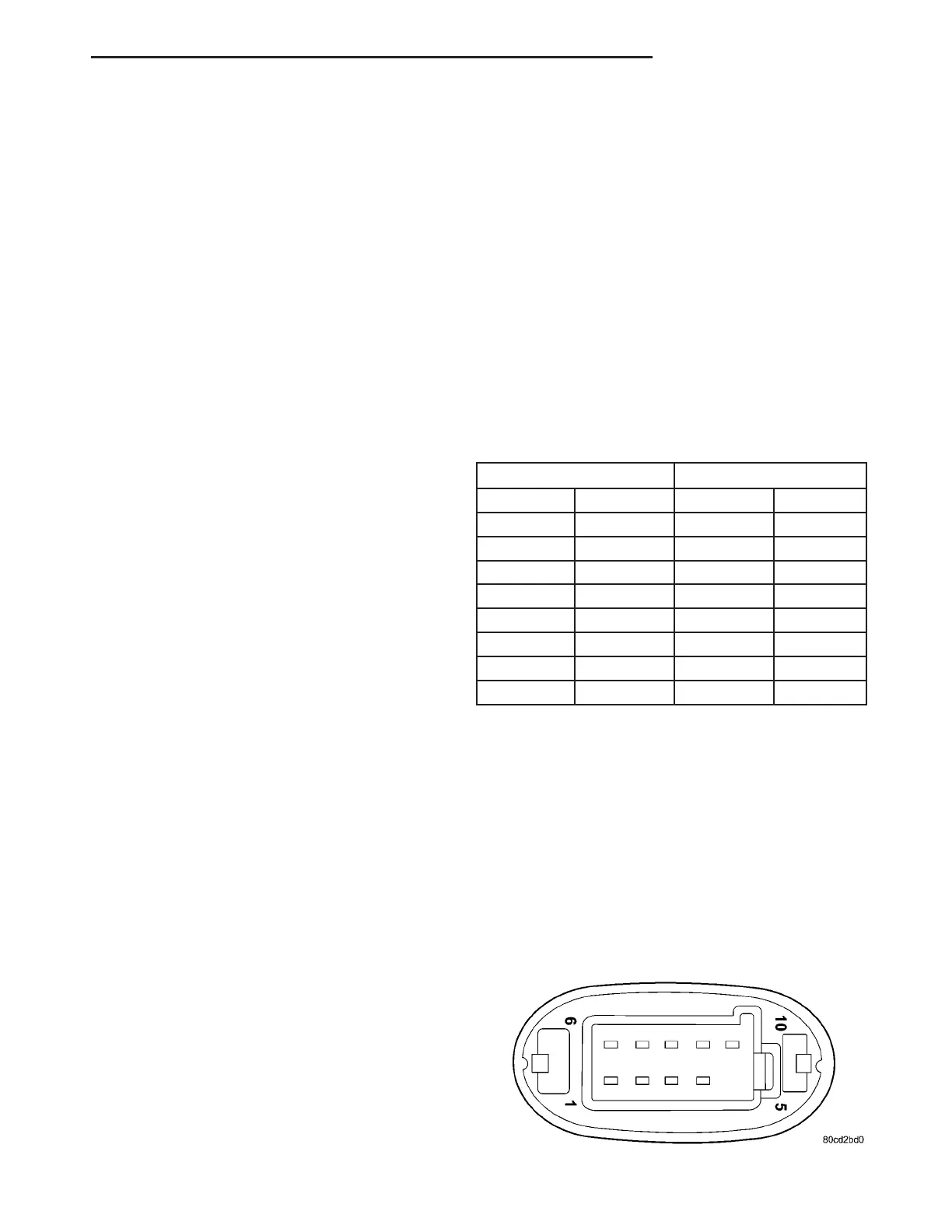
MIRROR MOTOR TEST
MIRROR REACTION
12 VOLT GROUND LEFT RIGHT
210 UP
81UP
10 2 DOWN
1 8 DOWN
9 10 RIGHT
4 1 RIGHT
10 9 LEFT
1 4 LEFT
POWER MIRROR SWITCH
DIAGNOSIS AND TESTING - POWER MIRROR
SWITCH
(1) Remove the power mirror switch (Refer to 8 -
ELECTRICAL/POWER MIRRORS/POWER MIRROR
SWITCH - REMOVAL).
(2)
Disconnect wiring harness connector from switch.
(3) Using a ohmmeter, test for continuity between
the terminals of the switch (Fig. 1).
(4) If results shown in the table are not obtained,
replace the switch.
Fig. 1 MIRROR SWITCH
ZB POWER MIRRORS 8N - 7