POWER WINDOW SWITCH
DESCRIPTION
The driver and passenger power window switches
are located on the center console bezel. The switches
are identical with a separate resistively multiplexed
input to the Body Control Module (BCM).
Each switch has four positions: Off/Diagnostic, Up,
Down and Auto Down. The switches are illuminated
by a Light Emitting Diode (LED) when the ignition
key is in the RUN position.
OPERATION
The power window switches provide an up or down
signal to the Body Control Module (BCM). The BCM
circuitry controls the output to the driver and pas-
senger door power window motors, and supplies elec-
trical current as required for the stand-alone
operation.
Each power window switch has two detent posi-
tions in the down direction. The first detent provides
normal power window operation. If this switch is
depressed to the second detent, the auto down cir-
cuitry of the BCM is activated. The auto-down cir-
cuitry will automatically move the door window to
the fully lowered position, even if the window switch
is released. The auto-down function will be automat-
ically cancelled and the window movement will be
stopped if the BCM detects a second input from the
same switch, in either direction.
DIAGNOSIS AND TESTING - POWER WINDOW
SWITCH
Any diagnosis of the Power Windows system
should begin with the use of scan tool and the
appropriate Diagnostic Service Manual.
Refer to the appropriate wiring information. The
wiring information includes wiring diagrams, proper
wire and connector repair procedures, details of wire
harness routing and retention, connector pin-out
information and location views for the various wire
harness connectors, splices and grounds.
Remove the switch (Refer to 8 - ELECTRICAL/
POWER WINDOWS/POWER WINDOW SWITCH -
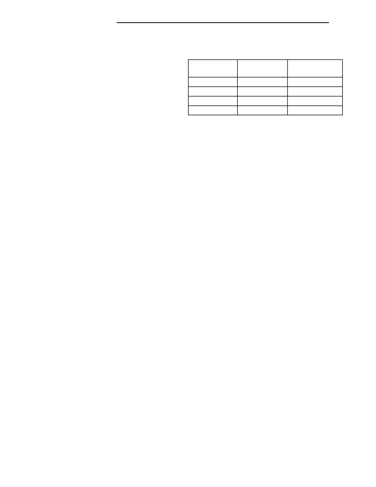
REMOVAL). Using an ohmmeter, refer to the power
window switch resistance test table to determine if
resistance is correct. If the correct results are not
obtained, replace the switch.
POWER WINDOW SWITCH CONTINUITY
SWITCH
POSITION
CONTINUITY
BETWEEN
RESISTANCE
VALUE
NEUTRAL Pins 2 and 3 4.8K Ohm ± 15%
UP Pins 2 and 3 600 Ohm ± 15%
DOWN Pins 2 and 3 340 Ohm ±15%
AUTO DOWN Pins 2 and 3 175 Ohm ± 15%
REMOVAL
NOTE: Each wire harness connector is marked left
or right, but can be interchanged between the two
switches.
(1) Disconnect and isolate the battery negative
cable.
(2) Remove the center console bezel (Refer to 23 -
BODY/INTERIOR/CENTER CONSOLE BEZEL -
REMOVAL).
(3) Remove switch from center console bezel.
INSTALLATION
NOTE: It is possible to interchange the connectors
between the two switches. Ensure that the windows
function properly after window switch installation.
(1) Install switch to center console bezel.
(2) Install the center console bezel (Refer to 23 -
BODY/INTERIOR/CENTER CONSOLE BEZEL -
INSTALLATION).
(3) Connect the battery negative cable.
WINDOW MOTOR
DESCRIPTION
Each door has a permanent magnet reversible elec-
tric motor with a hall effect sensor. This hall effect
sends an alternating signal (open/ground) to the
Body control Module (BCM) whenever the window
motor is moving.
The hall effect sensor and motor is serviced with
the regulator as an assembly (Refer to 23 - BODY/
DOOR - FRONT/WINDOW REGULATOR -
REMOVAL).
8N - 10 POWER WINDOWS ZB