CAUTION: Use a vise equipped with soft jaw caps
to protect the surface of the control arm from dam-
age.
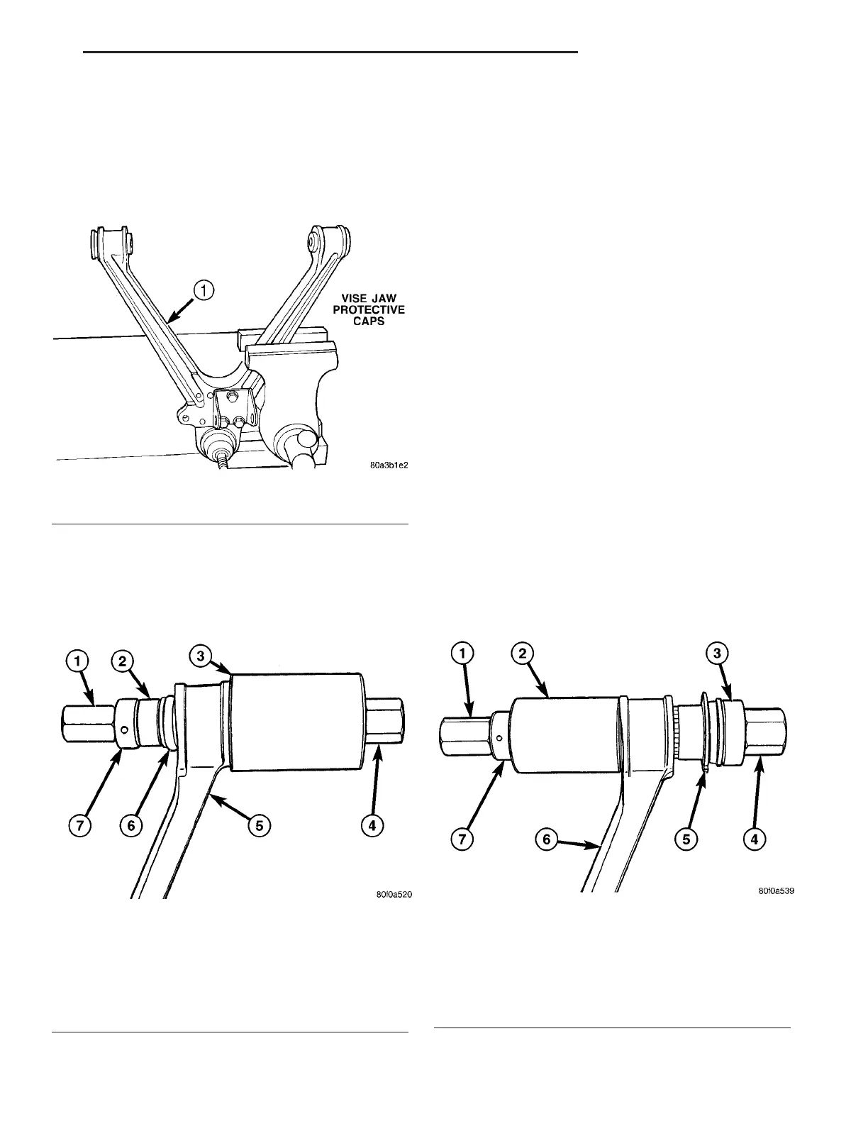
(1) Clamp lower control arm securely in vise so
that bushing to be removed is closest to vise jaws
(Fig. 22).
NOTE: Before using Special Tool 6969B, lubricate
threads of Screw Assembly 6969-3 with appropriate
lubricant.
(2) Assemble pieces of Remover, Special Tool
6969B, through bushing as shown (Fig. 23).
CAUTION: Do not use any type of impact wrench on
Special Tool 6969B. Use only hand tools.
(3) Hold Screw, Special Tool 6969-3, stationary
while rotating Nut, Special Tool 6969-4 clockwise.
This action will force isolator bushing out of control
arm, into Receiver, Special Tool 6969-2.
(4) Remove tools and bushing from arm. A small
portion of bushing rubber may come loose lodging
itself between Remover and control arm bushing
boar, causing some resistance during tool removal.
NOTE: For bushing installation, (Refer to 2 - SUS-
PENSION/FRONT/LOWER CONTROL ARM - ASSEM-
BLY).
ASSEMBLY - LOWER CONTROL ARM
(ISOLATOR BUSHINGS)
NOTE: The following procedure can be used for
either lower control arm isolator bushing.
(1) Squarely position isolator bushing into control
arm pivot end bore from outboard side.
NOTE: Before using Special Tool 6969B, lubricate
threads of Screw Assembly 6969-3 with appropriate
lubricant.
(2) Assemble pieces of Remover, Special Tool
6969B, through bushing and arm as shown (Fig. 24).
Fig. 22 Control Arm Mounted In Vise (Typical)
1 - LOWER CONTROL ARM
Fig. 23 Tool 6969B Installed For Bushing Removal
1 - DOUBLE THREADED NUT 6969-4
2 - SPACER 6969-1
3 - RECEIVER 6969-2
4 - SCREW ASSEMBLY 6969-3
5 - CONTROL ARM
6 - BUSHING
7 - BEARING
Fig. 24 Tool 6969B Installed For Bushing Installation
1 - DOUBLE THREADED NUT 6969-4
2 - CUP 6969-7
3 - INSTALLER 6969-8
4 - SCREW ASSEMBLY 6969-3
5 - NEW BUSHING
6 - CONTROL ARM
7 - BEARING
ZB FRONT SUSPENSION 2 - 15
LOWER CONTROL ARM (Continued)