CAUTION: Do not strike or apply heat to steering
knuckle in an effort to separate ball joint studs from
steering knuckle.
CAUTION: When releasing ball joint from knuckle
using Puller, Special Tool C-4150A, use care not to
pinch and damage ball joint grease seal.
(6) Install Puller, Special Tool C-4150A, over
knuckle and ball joint stud. Ball bearing in bolt of
Special Tool C-4150A must be centered in end of
upper ball joint stud.
(7) Release upper ball joint from knuckle using
Puller. Remove tools.
(8) Remove nuts and bolts attaching upper control
arm to mounting brackets on frame rail (Fig. 44).
Slightly spread ends of mounting brackets to ease
removal of control arm from brackets.
(9) Remove upper control arm.
DISASSEMBLY - UPPER CONTROL ARM
(ISOLATOR BUSHINGS)
NOTE: The following procedure can be used for
either upper control arm isolator bushing.
CAUTION: Use a vise equipped with soft jaw caps
to protect the surface of the control arm from dam-
age.
(1) Clamp upper control arm securely in vise so
that bushing to be removed is closest to vise jaws
(Fig. 45).
NOTE: Before using Special Tool 6969B, lubricate
threads of Screw Assembly 6969-3 with appropriate
lubricant.
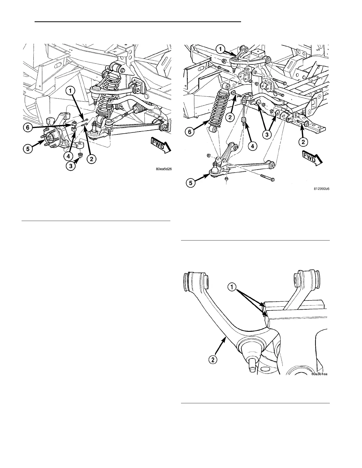
Fig. 43 Knuckle Mounting
1 - UPPER BALL JOINT COTTER PIN
2 - LOWER BALL JOINT COTTER PIN
3 - TIE ROD NUT
4 - LOWER BALL JOINT NUT
5 - KNUCKLE (WITH HUB AND BEARING)
6 - UPPER BALL JOINT NUT
Fig. 44 Front Suspension Mounting
1 - UPPER CONTROL ARM
2 - CAM BOLT
3 - CAM WASHER
4 - STABILIZER BAR LINK
5 - LOWER CONTROL ARM
6 - SHOCK ASSEMBLY
Fig. 45 Control Arm Mounted In Vise
1 - SOFT JAW VISE CAPS
2 - CONTROL ARM
ZB FRONT SUSPENSION 2 - 25
UPPER CONTROL ARM (Continued)