(3) Guide lower ball joint into lower control arm
and stabilizer link into mounting hole (Fig. 3). Install
ball joint castle nut. Tighten lower ball joint castle
nut to 160 N·m (118 ft. lbs.) torque.
(4) Install cotter pin in end of lower ball joint stud.
(5) Install stabilizer bar link nut and tighten to 23
N·m (17 ft. lbs.) torque.
(6) Install bolt and nut mounting shock assembly
clevis bracket to isolator bushing on lower control
arm. Do not tighten at this time.
(7) Install tire and wheel assembly (Refer to 22 -
TIRES/WHEELS - INSTALLATION). Progressively
tighten wheel mounting nuts in proper sequence to
122 N·m (90 ft. lbs.) torque.
(8) Lower vehicle.
(9) Position vehicle on alignment rack/drive-on
hoist.
(10) Set vehicle to design height. (Refer to 2 -
SUSPENSION/WHEEL ALIGNMENT - STANDARD
PROCEDURE - DESIGN HEIGHT MEASURE-
MENT)
(11) Tighten shock assembly clevis bracket mount-
ing bolt to 136 N·m (100 ft. lbs.) torque.
(12) Perform wheel alignment. (Refer to 2 - SUS-
PENSION/WHEEL ALIGNMENT - STANDARD
PROCEDURE)
(13) Road test vehicle to ensure proper operation.
LOWER CONTROL ARM
REMOVAL
NOTE: Review all Warnings and Cautions. (Refer to
2 - SUSPENSION - WARNING).
(1) Raise vehicle. (Refer to LUBRICATION &
MAINTENANCE/HOISTING - STANDARD PROCE-
DURE)
(2) Remove wheel and tire assembly. (Refer to 22 -
TIRES/WHEELS - REMOVAL)
(3) Remove nut and bolt mounting shock assembly
clevis bracket to isolator bushing on lower control
arm (Fig. 23).
CAUTION: The nut must be positioned at the end of
the stabilizer bar link stud when removing the link
from the lower control arm. This will prevent the
end of the stud from being damaged when remov-
ing it from the lower control arm.
(4) Remove stabilizer bar link from lower control
arm as follows:
(a) Loosen, but do not remove, nut attaching
rear stabilizer bar link to lower control arm (Fig.
14). Thread nut to end of stabilizer bar link stud.
(b) Position center punch in dimple on end of
link stud (Fig. 15).
(c) Strike center punch with hammer to remove
link stud from lower control arm.
(5) Remove cotter pin and castle nut from lower
ball joint stud (Fig. 16).
CAUTION: Do not strike or apply heat to steering
knuckle in an effort to separate ball joint studs from
knuckle.
NOTE: Use of Spacer, Special Tool 6983, is neces-
sary to allow proper use of Puller, Special Tool
C-4150A, to release lower ball joint from lower con-
trol arm.
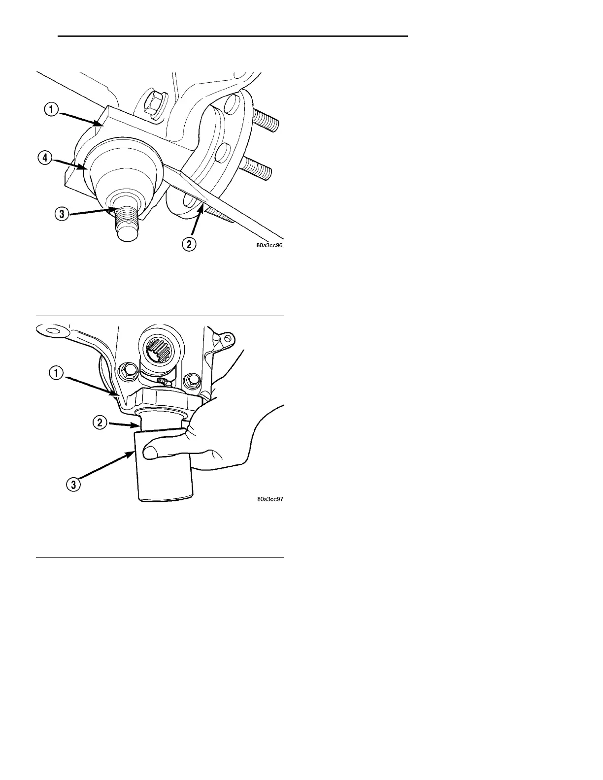
Fig. 12 Seal Boot Removal From Ball Joint
1 - REAR KNUCKLE
2 - SCREWDRIVER
3 - BALL JOINT
4 - SEAL BOOT
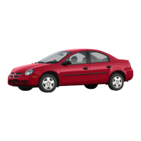
Fig. 13 Seal Boot Installation
1 - REAR KNUCKLE
2 - SEAL BOOT
3 - INSTALLER 6761
ZB REAR SUSPENSION 2 - 37
LOWER BALL JOINT SEAL BOOT (Continued)









 To Next Page