INSTALLATION
For proper main bearing size selection, refer to
MAIN BEARING SELECT FIT CHART.
MAIN BEARING SELECT FIT CHART
Engine Block
Mark
Crankshaft
Mark
Main Bearing
Color
White White Orange
White Black White
Black White White
Black Black Magenta
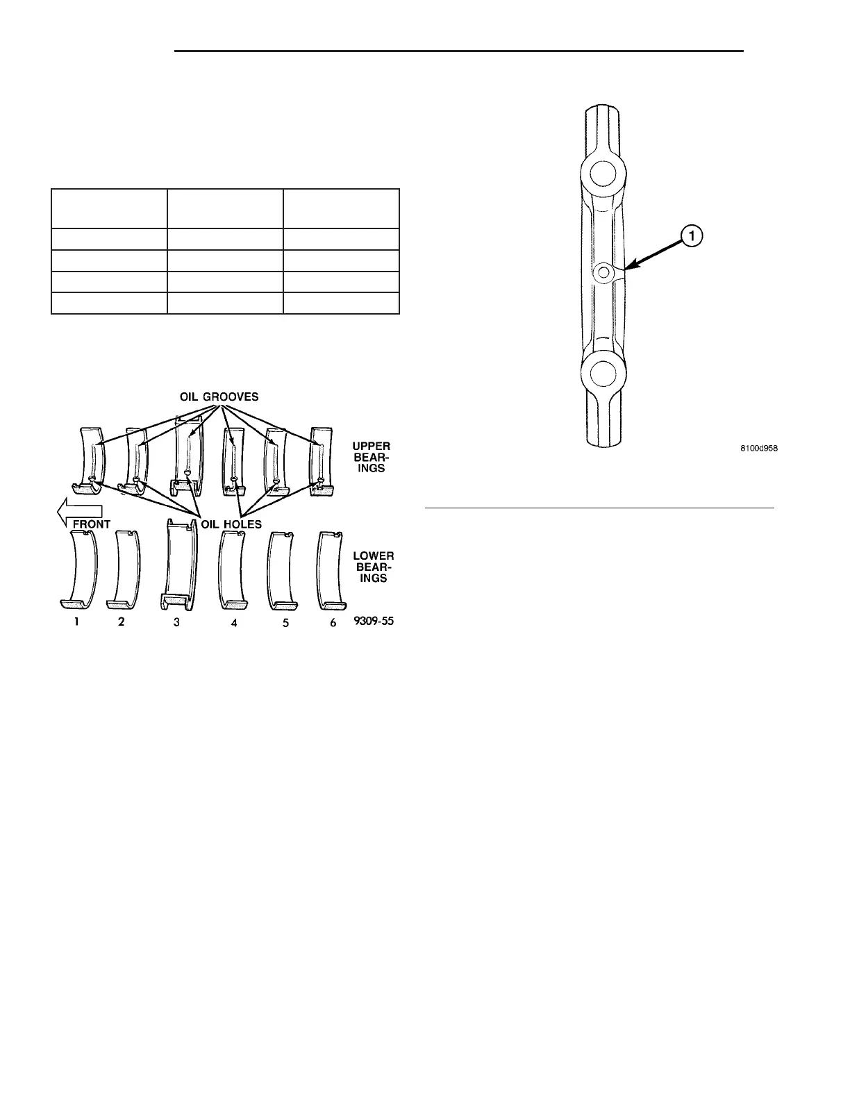
(1) Install upper main bearing shells into engine
block (Fig. 121).
(2) Lubricate upper main bearing shells with clean
engine oil.
(3) Install the crankshaft.
(4) Install lower main bearing shells into main
bearing caps (Fig. 121).
(5) Install each main bearing cap in proper
sequence and direction (Fig. 122). Tighten all bolts
finger tight.
(6) Tighten the main cap bolts in the following
tightening sequence:
• Step 1 Tighten main bearing cap bolts 1–12 in
the sequence order shown in (Fig. 123) to 20 N·m (15
ft. lbs.). This will seat the bearing caps onto the
engine block.
• Step 2 To ensure correct thrust bearing align-
ment the following procedure must be done:
a. Move crankshaft all the way to the rear of its
travel.
b. Then, move crankshaft all the way to the
front of its travel.
c. Wedge an appropriate tool between the rear of
the cylinder block and rear crankshaft counter-
weight. This will hold the crankshaft in it’s most
forward position.
• Step A1—tighten the A1 bolts to 61 N·m (45 ft.
lbs.) in the sequence order shown in (Fig. 123).
• Step A2—tighten the A2 bolts to 115 N·m (85 ft.
lbs.) in the sequence order shown in (Fig. 123).
• Step A3—tighten the A3 Bolts to 54 N·m (40 ft.
lbs.) in the sequence order shown in (Fig. 123).
(7) Remove the holding tool.
(8) Install new connecting rod bearings.
(9) Install rod caps. Install NEW connecting rod
bolts. Bolt threads should be oiled with engine oil.
Torque connecting rod bolts to 68 N·m (50 ft. lbs.).
(10) Install the crankshaft oil scraper and tighten
nuts to 23 N·m (200 in. lbs.) (Fig. 118).
(11) Install oil pump pick up tube using a new
o-ring. Torque 1/4–20 bolt to 11 N·m (95 in. lbs.).
Torque 5/16–18 nut to 23 N·m (200 in. lbs.) (Fig.
117).
(12) Install the crankshaft rear oil seal and
retainer (Refer to 9 - ENGINE/ENGINE BLOCK/
CRANKSHAFT REAR OIL SEAL RETAINER -
INSTALLATION).
Fig. 121 Main Bearing Identification
Fig. 122 Main Bearing Cap Orientation
1 - MARKING FACES FRONT OF ENGINE
9 - 70 ENGINE ZB
CRANKSHAFT (Continued)











 To Next Page