(5) Tighten spout assembly band clamp to 54 N·m
(40 ft. lbs.).
(6) Install sill panel (Refer to 23 - BODY/EXTERI-
OR/SILL PANEL - INSTALLATION) (Fig. 7).
(7) Lower vehicle.
(8) Start the engine and inspect for exhaust leaks.
Repair exhaust leaks as necessary.
(9) Check the exhaust system for contact with the
body panels. Make the necessary ajustments, if
needed.
SPOUT ASSEMBLY - LEFT/
RIGHT
REMOVAL
NOTE: This procedure covers removal of either the
right OR left spout assembly. Remove the appropri-
ate parts for the side that is being worked on.
(1) Raise vehicle on hoist (Refer to LUBRICATION
& MAINTENANCE/HOISTING - STANDARD PRO-
CEDURE).
(2) Remove sill panel (Refer to 23 - BODY/EXTE-
RIOR/SILL PANEL - REMOVAL) (Fig. 7).
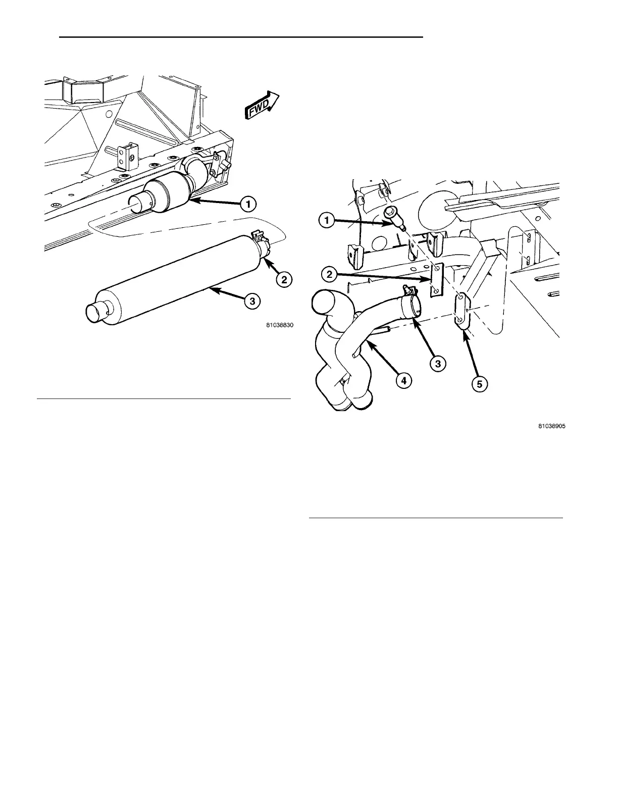
(3) Apply penetrating oil to spout assembly and
H-pipe band clamps (Fig. 11) and (Fig. 12).
(4) Loosen spout assembly and H-Pipe band
clamps (Fig. 11) and (Fig. 12).
(5) Remove “B” pillar support isolator (Fig. 11).
(6) Separate spout assembly from resonator.
(7) Separate spout assembly from H-Pipe.
(8) Remove spout assembly.
INSTALLATION
NOTE: This procedure covers installation of either
the right OR left spout assembly. Install the appro-
priate parts for the side that is being worked on.
(1) Connect spout assembly to H-Pipe (Fig. 12). Do
not tighten band clamps at this time.
(2) Connect spout assembly to resonator (Fig. 11).
Do not tighten band clamp at this time.
(3) Install “B” pillar support isolator. Tighten bolts
to 28 N·m (250 in. lbs.) (Fig. 11).
(4) Tighten band clamps to 54 N·m (40 ft. lbs.).
(5) Install sill panel (Refer to 23 - BODY/EXTERI-
OR/SILL PANEL - INSTALLATION) (Fig. 7).
(6) Lower vehicle.
Fig. 10 Resonator (Right Side Shown - Left Side
Typical)
1 - CATALYTIC CONVERTER
2 - BAND CLAMP
3 - RESONATOR
Fig. 11 Spout Assembly Mounting (Right Side
Shown - Left Side Typical)
1 - BOLT(S)
2 - BRACKET
3 - BAND CLAMP
4 - SPOUT ASSEMBLY
5-9B9 PILLAR SUPPORT ISOLATOR
ZB EXHAUST SYSTEM 11 - 9
RESONATOR(S) (Continued)















 To Next Page