(2) If sectioning, refer to front upper frame rail
assembly in this section.
(3) Double check all measurements (Refer to 13 -
FRAME & BUMPERS/FRAME - SPECIFICATIONS -
FRAME DIMENSIONS).
(4) Complete welding (Refer to 13 - FRAME &
BUMPERS/FRAME - SPECIFICATIONS - WELD-
ING).
(5) Dress the welded area and apply corrosion
resistant coatings inside and out.
(a) Apply etch-primer to the inside of the frame
rail repair area.
(b) Inside the rail, inject a creeping wax based
rust inhibitor compound through the existing holes
in the frame ensuring 100% coverage including the
space between the original frame rail and the rein-
forcing sleeve.
(c) Apply a durable top coat to the outside of the
repair area.
SPECIFICATIONS
FRAME DIMENSIONS
A vehicle is designed within a three dimensional
grid partitioned into 100 mm (3.92 in.) cubes. The
lines that make up the grid run in three planes
defined as X, Y, and Z. The X-plane extends from the
front to the rear of the vehicle. The Y-plane extends
from the center line (C/L) of the vehicle outward. The
Z-plane extends from Datum 312 mm (12.28 in.)
below the frame rails upward. Most Y-plane dimen-
sions are symmetric to the C/L.
Frame dimensions are listed in metric scale. All
dimensions are from center of Principal Locating
Point (PLP), or from center to center of PLP and fas-
tener location. The tolerance on all dimensions,
except for suspension locations, is ± 3 mm. The tol-
erance on all dimensions for suspension locations is ±
2 mm.
VEHICLE PREPARATION
Position vehicle on a level work surface. Using
suitable lifting devices and fixtures, adjust the vehi-
cle PLP heights to the specified dimensions above the
work surface.
FRAME DIMENSION INDEX
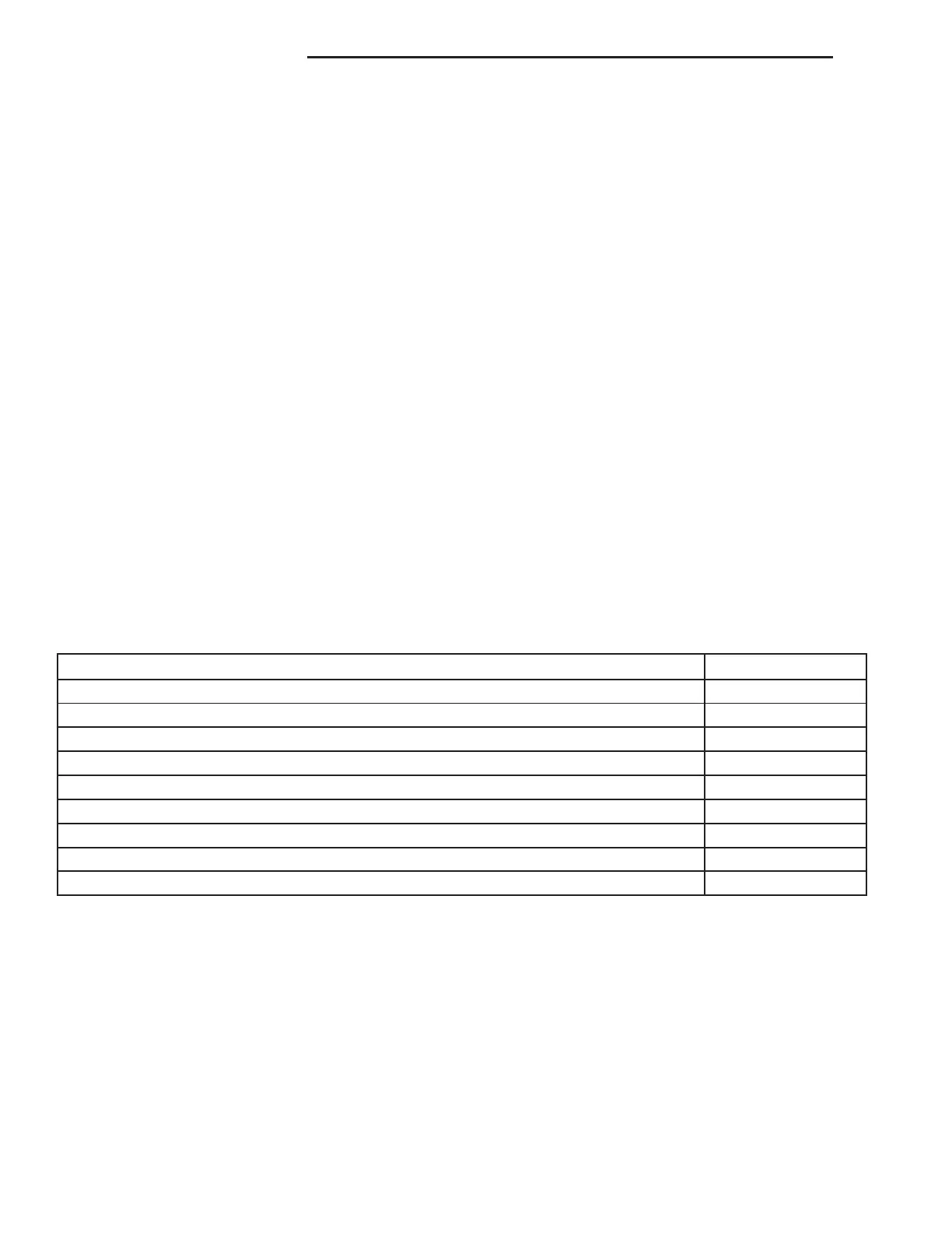
DESCRIPTION FIGURE
X, Y, AND Z PLANES 15
FRAME SIDE VIEW - FRONT SECTION - Z DIMENSIONS 16
FRAME SIDE VIEW - REAR SECTION - Z DIMENSIONS 17
FRAME SIDE VIEW - FRONT SECTION - X DIMENSIONS 18
FRAME SIDE VIEW - REAR SECTION - X DIMENSIONS 19
FRAME TOP VIEW - FRONT SECTION - X AND Y DIMENSIONS 20
FRAME TOP VIEW - REAR SECTION - X AND Y DIMENSIONS 21
FRONT SUSPENSION MOUNTING ANGLES 22
REAR SUSPENSION MOUNTING ANGLES 23
13 - 12 FRAME & BUMPERS ZB
FRAME (Continued)












 To Next Page