FUEL DELIVERY
DESCRIPTION
FUEL DELIVERY SYSTEM
The fuel delivery system consists of: the electric
fuel pump, fuel filter, fuel pressure regulator, fuel
tubes/lines/hoses, fuel rail, fuel injectors, fuel tank,
accelerator pedal and throttle cable.
The in-tank fuel pump module contains the fuel
pump, level sensor, and fuel pressure regulator. The
pump, and regulator are serviced as part of the fuel
pump module. Refer to Fuel Pump Module.
LONG-TERM STORAGE
When storing your vehicle for long periods, leave
the fuel tank and fuel system full of fuel. For further
information about long-term vehicle storage, refer to
the Lubrication and Maintenance section.
OPERATION - FUEL DELIVERY SYSTEM
A fuel return system is used on all models. Fuel is
returned through the fuel pressure regulator within
the fuel pump module.
The fuel tank assembly consists of: the fuel tank,
filler tube, fuel gauge sending unit/electric fuel pump
module, rollover valve, ORVR control valve, fuel fill
check valve, and a pressure-vacuum filler cap.
Also to be considered part of the fuel system is the
evaporation control system. This is designed to
reduce the emission of fuel vapors into the atmo-
sphere. The description and function of the Evapora-
tive Control System is found in the Emission Control
Systems.
STANDARD PROCEDURE
FUEL SYSTEM PRESSURE RELEASE
PROCEDURE
(1) Remove Fuel Pump relay from Power Distribu-
tion Center (PDC). For location of relay, refer to label
on underside of PDC cover.
(2) Start and run engine until it stalls.
(3) Attempt restarting engine until it will no
longer run.
(4) Turn ignition key to OFF position.
(5) Return fuel pump relay to PDC.
(6) One or more Diagnostic Trouble Codes (DTC’s)
may have been stored in PCM memory due to fuel
pump relay removal. The DRB IIIt scan tool must be
used to erase a DTC.
DRAINING FUEL TANK
(1) Release fuel system pressure. Refer to Fuel
Pressure Release Procedure in this section.
(2) Remove the fuel pump module, refer to the fuel
pump module removal/installation in this section.
(3) Drain fuel from fuel tank into siphoning tank.
Refer to the siphoning tank Manufacturer’s Instruc-
tions.
SPECIFICATIONS
FUEL SYSTEM PRESSURE
379 kpa ±34 kpa (55 psi ± 5 psi)
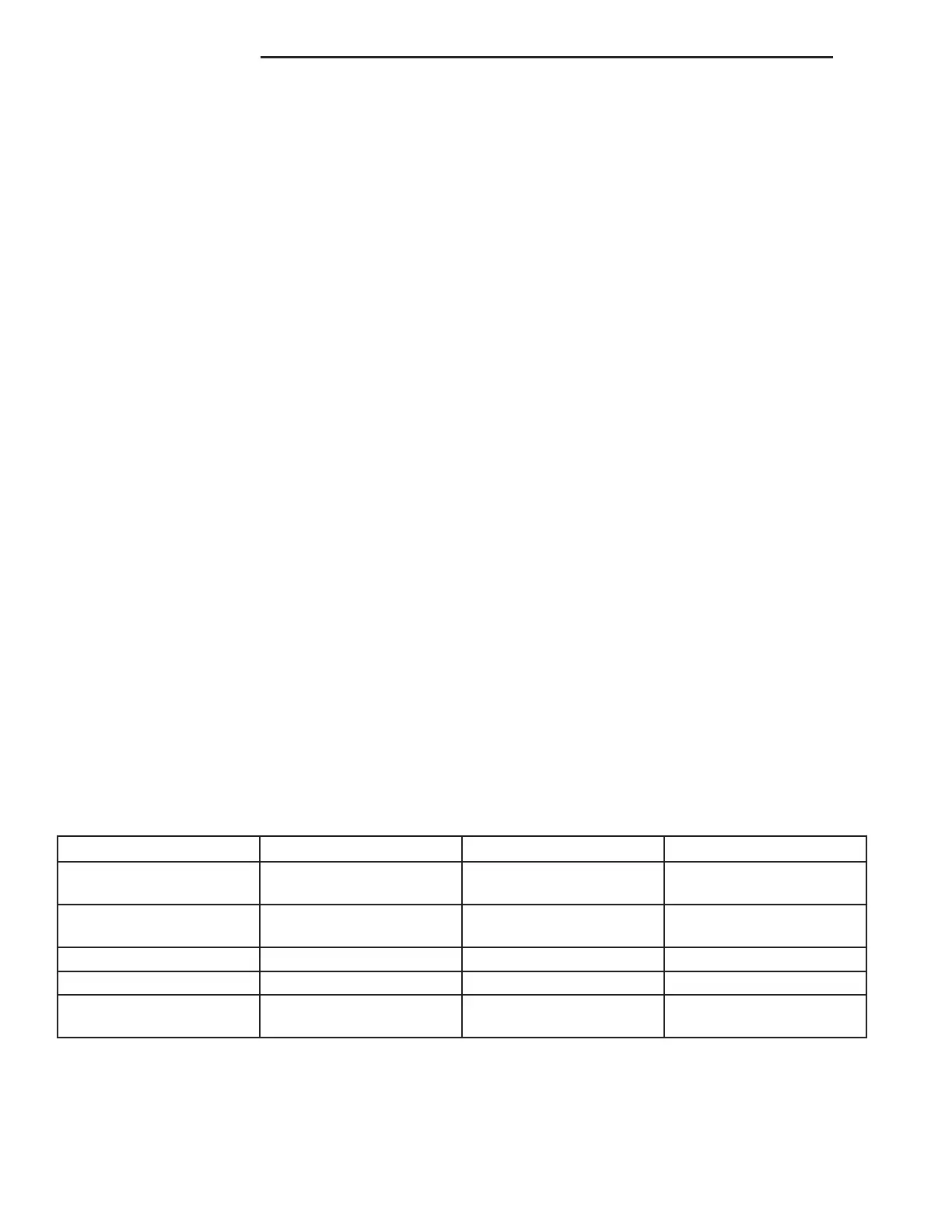
TORQUE
DESCRIPTION N·m Ft. Lbs. In. Lbs.
Accelerator Pedal to Dash
Nuts
12 105
Fuel Pump Module Lock-
nut
55 40
Fuel Tank Strap Bolts 22.5 200
Fuel Rail Bolts 12 105
Ignition Coil Mounting
Bolts
11 95
14 - 2 FUEL DELIVERY ZB
 Loading...


