SPECIFICATIONS
TORQUE SPECIFICATIONS
DESCRIPTION N·m Ft. Lbs. In. Lbs.
Adapter Bolts 34 25 -
Back-up Lamp Switch 34 25 -
Dust Shield Bolts 11 - 95
Clutch Release Bearing 20 15 -
Drain Plug 38 28 -
Fill Plug 27 20 -
Flywheel Bolts 74 55 -
Guide Plate Bolts 22 16 -
Inspection Plug 27 20 -
Interlock Bolt 27 20 -
*Reverse Idler Brkt. Bolts 24 18 -
Reverse Inhibitor Bolt 18 13 -
Shifter Assembly 20 15 -
*Shift Detent Assembly 34 25 -
Skip Shift Solenoid 34 25 -
Trans. Top Cover Bolts 20 15 -
Trans. Crossmember
Bolts
61 45 -
Trans. Mount Bolts 41 30 -
Trans. To Eng. Bolts (3/8) 41 30 -
Trans. To Eng. Bolts
(7/16)
68 50 -
Trans. To Oil Pan (5/16) 23 - 200
*U-joint Clamp Bolts 19 14 170
* Needs application of LoctiteT 242
SPECIAL TOOLS
EXTENSION HOUSING SEAL
REMOVAL
(1) Remove belly pan.
(2) Remove propeller shaft.
(3) Remove seal with Remover C-3985-B (Fig. 115).
(4) Clean and inspect extension housing where the
seal was located.
INSTALLATION
(1) Install seal into place with Installer 8889.
(2) Install propeller shaft.
CAUTION: The drive shaft strap bolts use a Loctite
patch, the bolts must be replaced or cleaned and
LoctiteT 242 applied.
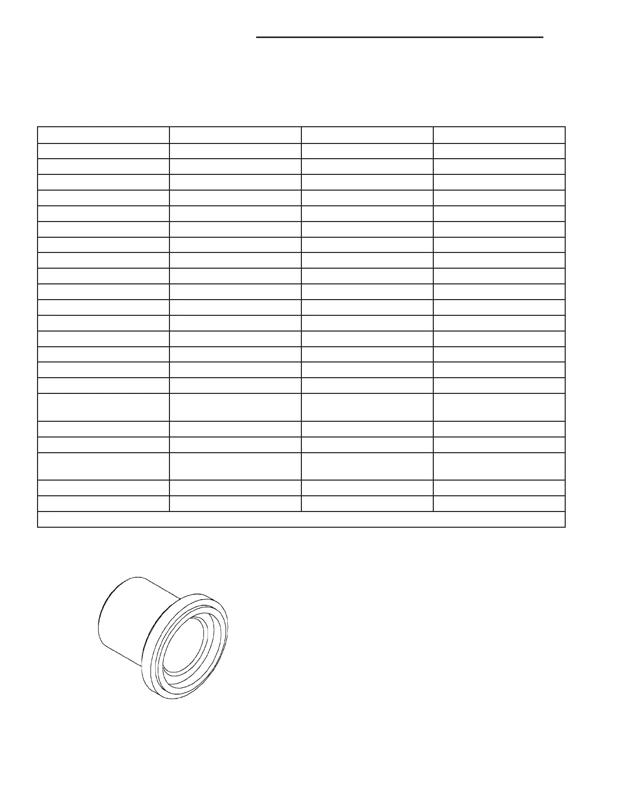
INSTALLER 8889
21 - 36 MANUAL TRANSMISSION - T56 ZB
MANUAL TRANSMISSION - T56 (Continued)















 To Next Page