STANDARD PROCEDURE
TIRE AND WHEEL BALANCE
Balancing need is indicated by vibration in seats,
floor pan, or steering wheel. The vibration will be
noticed mostly when driving over 95 km/h (60 mph)
on a smooth road.
It is recommended that a two-plane dynamic bal-
ancer be used when a wheel and tire assembly
requires balancing. Static balancing equipment
should only be used when a two-plane balancer is not
available.
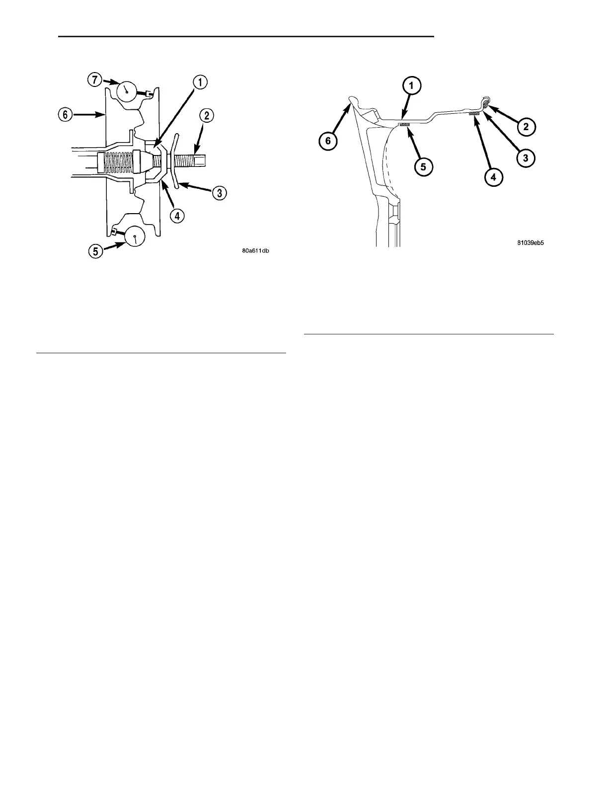
This vehicle is equipped with wheels that do not
have a flange on the outer face. For that reason,
clip-on wheel weights cannot be used on the outer
face of any wheel, and can only be used on the inner
face of the front wheels (Fig. 6). They must not be
used on the rear wheel inner face due to clearance
issues. In their place, stick-on type weights must be
used. Wheel weights may be placed in locations indi-
cated in figure (Fig. 6).
For static imbalance, find the location of the heavy
spot causing the imbalance. Counter balance the
wheel and tire directly opposite the heavy spot.
Determine weight required to counterbalance the
area of imbalance. Place half of this weight on the
inner rim flange and the other half on the rim
between the outer face and the weld using tape on
wheel weights. (Fig. 7) and (Fig. 8). Off-vehicle bal-
ancing is necessary.
Wheel balancing can be accomplished with either
on or off vehicle equipment. When using on-vehicle
balancing equipment, remove the opposite wheel/tire.
TIRE AND WHEEL MATCH MOUNTING
Wheels and tires are match mounted at the factory.
This means that the high spot of the tire is matched
to the low spot on the wheel rim. This technique is
used to reduce run-out in the wheel/tire assembly.
The high spot on the tire is marked with a paint
mark or a bright colored adhesive label on the out-
board sidewall. The low spot on the rim is identified
with a label on the outside of the rim and a dot or
line in the drop well on the tire side of the rim. If the
outside label has been removed the tire will have to
be removed to locate the dot or line on the inside of
the rim.
Before dismounting a tire from its wheel, a refer-
ence mark should be placed on the tire at the valve
stem location. This reference will ensure that it is
remounted in the original position on the wheel.
Fig. 5 Checking Lateral Runout Of Wheel
1 - MOUNTING CONE
2 - SPINDLE SHAFT
3 - WING NUT
4 - PLASTIC CUP
5 - DIAL INDICATOR
6 - WHEEL
7 - DIAL INDICATOR
Fig. 6 Wheel Weight Locations
1 - WHEEL
2 - CLIP-ON WHEEL WEIGHT (FRONT WHEELS ONLY)
3 - INNER FACE OF WHEEL
4 - STICK-ON WHEEL WEIGHT (INNER LOCATION)
5 - STICK-ON WHEEL WEIGHT (OUTER LOCATION)
6 - OUTER FACE OF WHEEL
ZB TIRES/WHEELS 22 - 3
TIRES/WHEELS (Continued)















 To Next Page