REMOVAL - TIRE AND WHEEL ASSEMBLY
(1) Raise the vehicle. (Refer to LUBRICATION &
MAINTENANCE/HOISTING - STANDARD PROCE-
DURE)
(2) Remove the 6 wheel mounting nuts securing
the wheel to the hub.
(3) Remove the tire and wheel assembly by pulling
it straight away from the hub.
INSTALLATION - TIRE AND WHEEL ASSEMBLY
NOTE: Before installing the wheel on the hub, be
sure to remove any buildup of corrosion on the
mounting surface of the wheel and the hub. Install-
ing wheels without good metal-to-metal contact
could cause loosening of the wheel nuts. This
could adversely affect the safety and handling of
the vehicle.
(1) Position the tire and wheel assembly on the
vehicle by aligning the wheel mounting studs with
the 6 mounting holes in the wheel and slide the
assembly onto the hub.
NOTE: Never use oil or grease on the studs or
wheel attaching nuts.
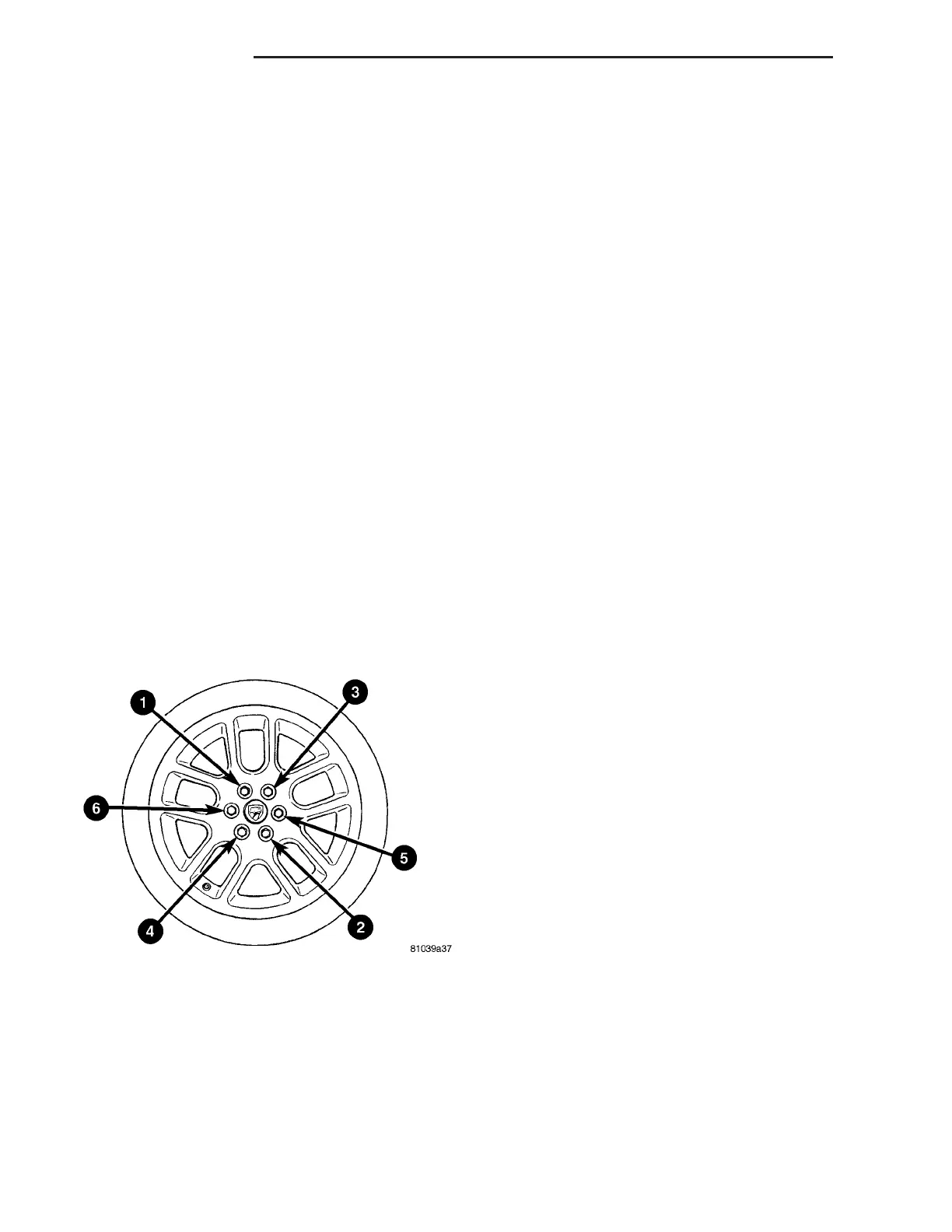
(2) Install all 6 wheel mounting nuts and lightly
tighten each. Progressively tighten each nut in
sequence to a torque of 122 N·m (90 ft. lbs.) (Fig. 12).
(3) Lower the vehicle.
TIRE PRESSURE MONITORING
(TPM)
DESCRIPTION
This vehicle has a tire pressure monitoring (TPM)
system as standard equipment. It is there to alert
the driver when air pressure in any of the vehicle’s
four tires falls below a predetermined threshold or if
there is a failure in one of the TPM components.
TPM alerts the driver with 9LO TIRE9 displayed in
the cluster odometer and an audible chime tone. For
Operation information, (Refer to 22 - TIRES/
WHEELS/TIRE PRESSURE MONITORING - OPER-
ATION)
The TPM system utilizes these main components:
• Tire Pressure Monitoring Module
• Tire Pressure Sensor/Transmitters (Four - One
in each wheel)
• Cluster Odometer Message “LO TIRE”
• Body Control Module (communication link)
For information on specific components, refer to
that individual component.
OPERATION
The Tire Pressure Monitoring (TPM) system oper-
ates by monitoring a radio frequency transmission
from the tire pressure sensor/transmitters located in
each wheel, and integrated with the valve stem.
When the vehicle reaches a speed of approximately
32 km/h (20 mph), centrifugal force created by the
wheels rotating closes a roll switch inside each sen-
sor, powering up the circuitry. To facilitate transmit-
ting the radio signal to the TPM module, the valve
stem acts as the antenna for the tire pressure sensor/
transmitter.
The Body Control Module (BCM) monitors the tire
pressure signal that is sent from the TPM module
when the ignition key is in RUN/START position.
When the BCM receives the tire pressure signal it
will send a corresponding bus message to the cluster.
If the BCM message indicates a fault, then the clus-
ter will display in the odometer 9LO TIRE9 and send
a chime request message to the BCM.
POWER UP INITIALIZATION
When the ignition is turned to RUN, the TPM out-
put signal is grounded for 2 seconds, then goes open.
If this sequence does not occur, then the BCM regis-
ters the Tire Module Initialization fault (DTC). Once
this fault is matured (10 seconds), the BCM sends a
bus message to the cluster. The cluster will display
9LO TIRE9 steady on and send a single chime request
to the BCM.
Fig. 12 Wheel Nut Tightening Sequence
22 - 6 TIRES/WHEELS ZB
TIRES/WHEELS (Continued)















 To Next Page