• Front and rear upper control arm to frame
bracket mounting bolts.
• Front and rear shock assembly to frame bracket
mounting bolts.
• Front and rear shock assembly to lower control
arm mounting bolts.
NOTE: When loosening the lower control arm
mounting bolts, be sure the alignment adjustment
cams do not turn. The cams must stay in their orig-
inal position so the alignment of the vehicle is not
affected.
NOTE: The mounting bolts must be loosened
enough to allow the suspension of the vehicle to
move without loading (twisting) the rubber insert of
the isolator bushings.
(15) Tighten previously loosened mounting bolts to
specified torque values. (Refer to 2 - SUSPENSION/
FRONT - SPECIFICATIONS) (Refer to 2 - SUSPEN-
SION/REAR - SPECIFICATIONS)
• Front and rear lower control arm to frame
bracket cam adjustment bolts and nuts.
• Front upper control arm to frame bracket
mounting bolts.
• Rear upper control arm to frame bracket mount-
ing bolts.
• Front and rear shock assembly to frame bracket
mounting bolts.
• Front shock assembly to lower control arm
mounting bolts.
• Rear shock assembly to lower control arm
mounting bolts.
(16) Remove Suspension Height Gages from vehi-
cle.
(17) If wheel alignment is to be performed, proceed
at this point. (Refer to 2 - SUSPENSION/WHEEL
ALIGNMENT - STANDARD PROCEDURE -
WHEEL ALIGNMENT)
(18) Install belly pan. (Refer to 23 - BODY/EXTE-
RIOR/BELLY PAN - INSTALLATION)
(19) Remove ballast weight from vehicle, allowing
vehicle to return to curb height.
WHEEL ALIGNMENT
NOTE: Wheel alignment must be checked and
adjusted to the preferred specifications with the
vehicle at Design Height rather than at Curb Height.
(1) Place vehicle on wheel alignment rack or
drive-on lift per equipment manufacturer’s recom-
mendations.
(2) Perform pre-wheel alignment inspection. (Refer
to 2 - SUSPENSION/WHEEL ALIGNMENT - STAN-
DARD PROCEDURE - PRE-WHEEL ALIGNMENT
INSPECTION)
(3) Set vehicle to specified design height. (Refer
to 2 - SUSPENSION/WHEEL ALIGNMENT - STAN-
DARD PROCEDURE - DESIGN HEIGHT MEA-
SUREMENT)
(4) Remove Suspension Height Gages, Special
Tools 6914 and 8897, from vehicle.
(5) Attach wheel alignment equipment following
equipment manufacturer’s instructions.
NOTE: Align the vehicle starting with the rear sus-
pension, then proceed to the front suspension.
Always set toe last.
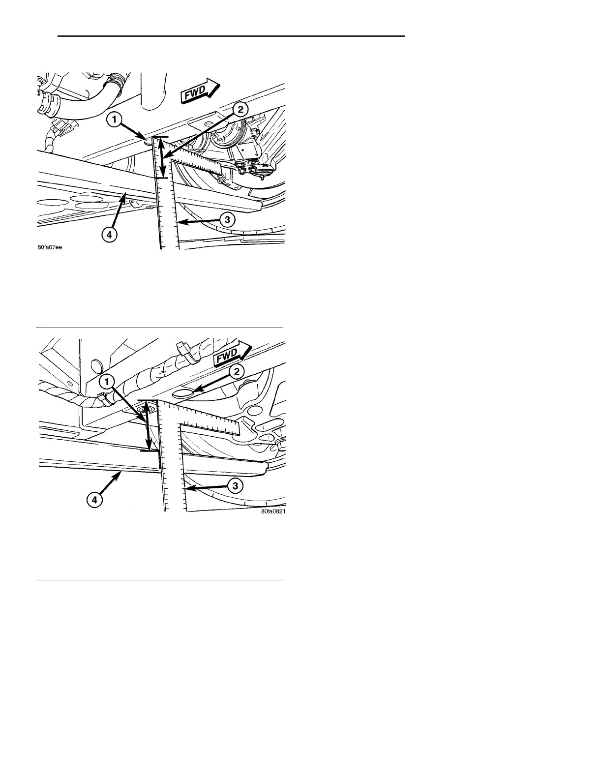
Fig. 12 Measuring Vehicle Height - Front
Suspension
1 - PLP HOLE
2 - MEASURE THIS DISTANCE
3 - MEASURING DEVICE
4 - HEIGHT GAGE 6914
Fig. 13 Measuring Vehicle Height - Rear Suspension
1 - MEASURE THIS DISTANCE
2 - PLP HOLE
3 - MEASURING DEVICE
4 - HEIGHT GAGE 6914
ZB WHEEL ALIGNMENT 2 - 65
WHEEL ALIGNMENT (Continued)
 Loading...


