Attach the other cover on the assembly profile in the same way.
Check the outer lever handle for flawless functioning (coupling).
If the outer lever handle does not couple flawlessly, align it as follows:
Remove the cover of the outer handle as described in section “Removing
handle” from page 234 onwards.
Align the outer lever handle horizontally as described from page 60
onwards.
The horizontal positions of the outer lever handle and inner lever handle must
match.
Reattach the cover to the assembly profile.
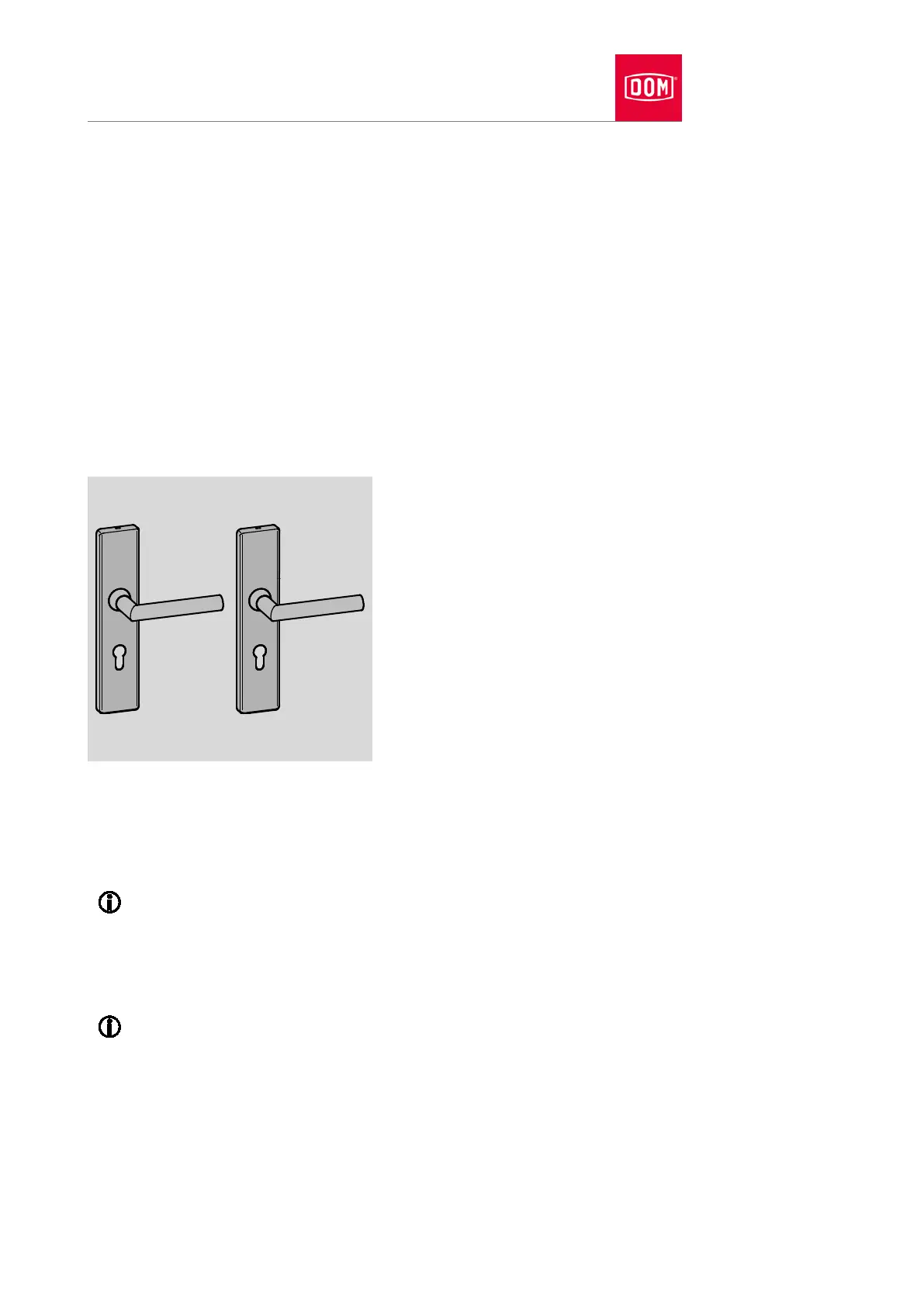
Mechanical GUARD Wideline set
Installing handle and screwing right through
You must attach the spindle on the handle and align the lever handle prior to
attaching the handle.
The alignment of the lever handle on the handle is described from
page
58 onwards.
ent of the spindle is described from page 63 onwards.
The attachment of the spindle with reducing bushes is described from
page 66 onwards.
An electronic GUARD Slimline long plate is presented in the section
which follows.
The assembly profiles are attached on both sides of the door and screwed
together. Threaded bushes are inserted into the outer assembly profile for this
purpose. The inner assembly profile is attached with long screws which are
screwed into the threaded bushes.