Power Supply Input Connector Layout (Gx-OEM)
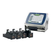
The power supply input connector pin assignment is illustrated below.
Note
Only 1 x 24 V Input pin and 1 x Ground pin needs to be connected to the power
supply.
S2C 3.5mm, 4 Way, Terminal Block (External View)
Pin Description Pin Description
1 Ground 3 24 V DC, 4 A Input
2 Ground 4 24 V DC, 4 A Input
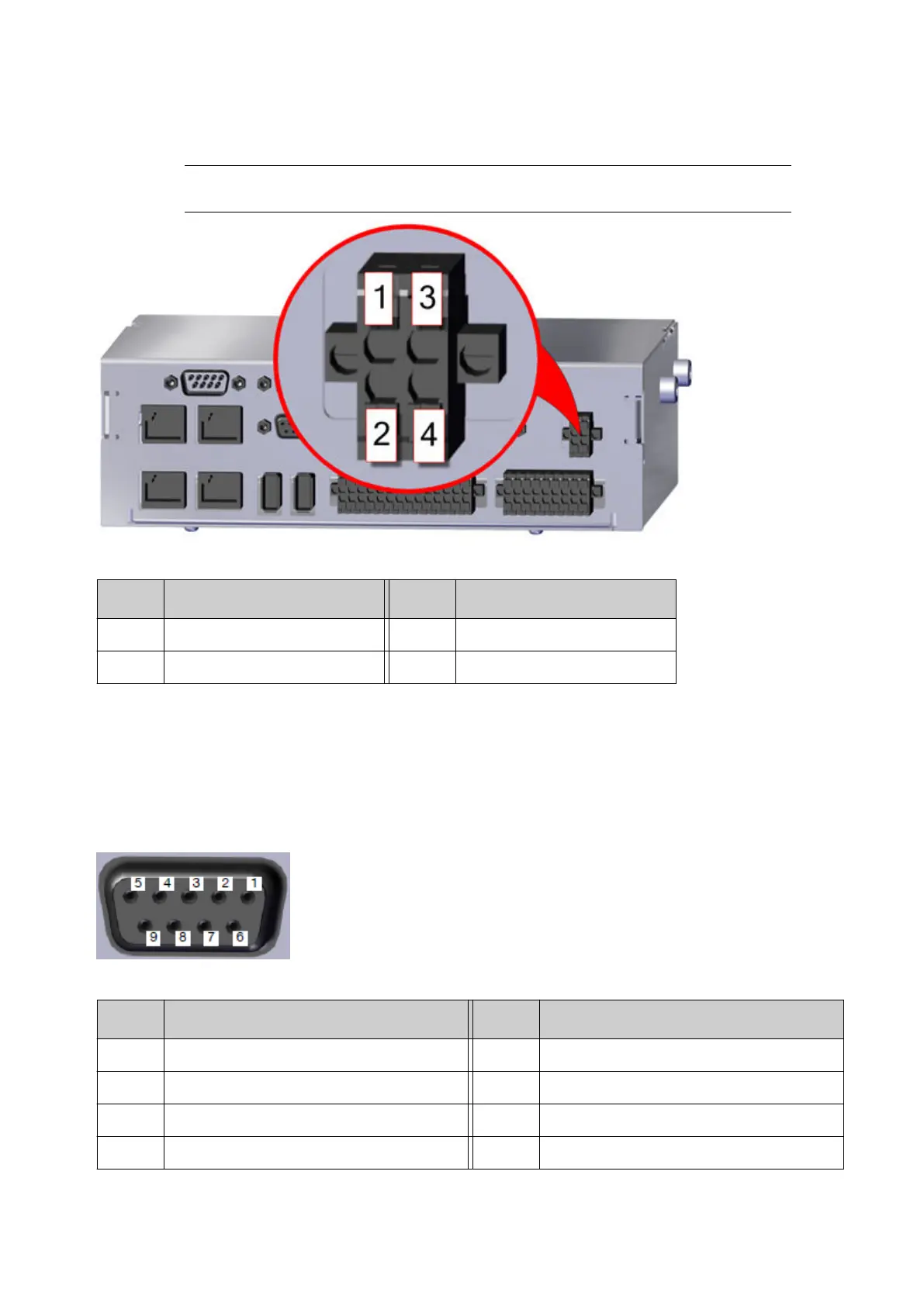
Encoder Connector Layout
Gx-IC7 controllers have 1 encoder connector.
Gx-IC10 and Gx-OEM controllers have 2 encoder connectors, ENC1 and ENC2 (RS422
standard).
The pin assignments are illustrated below.
D-Sub Socket (External View)
Pin Description Pin Description
1 24 V 6 Not Used
2 Ground 7 Not Used
3 Not Used 8 Encoder Channel B+
4 Encoder Channel A+ 9 Encoder Channel B-
INSTALLATION
EPT053091 - Issue 5 - 07 May 2021 36
 Loading...