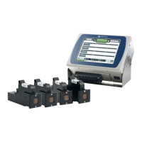
The connection depends on the PLC's output type. The diagram below illustrates a 0 V input
from the PLC.
To define input functions, see Inputs on page 82.
Gx-IC7 PLC Input (0 V from PLC)
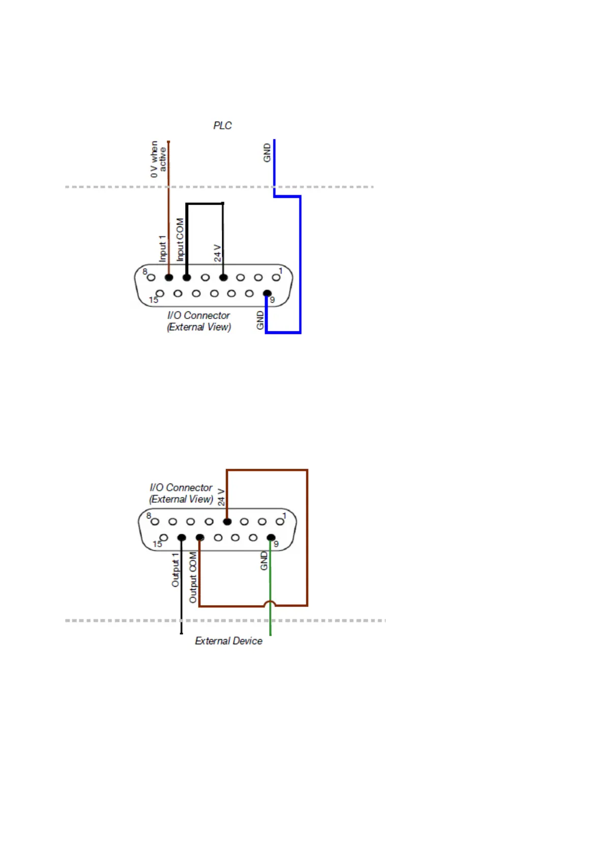
Output (24 V When Active)
2 outputs are available on each of the I/O connectors. The diagram below illustrates the
connection to "Output 1" on one of the I/O connectors. The other outputs are listed see I/O
Connector Layout (Gx-IC7) on page 37.
To define output functions, see Inputs on page 82.
Gx-IC7 Output (24 V When Active)
Output (0 V When Active)
2 outputs are available on each of the I/O connectors. The diagram below illustrates the
connection to "Output 1" on one of the I/O connectors. The other outputs are listed see I/O
Connector Layout (Gx-IC7) on page 37.
INSTALLATION
EPT053091 - Issue 5 - 07 May 2021 42
 Loading...