63
6. Machine Accuracy Measurement and Adjustment
※ Note) Table Ass’y vertical/horizontal adjustment
(1) When the B-axis is turned to B90, make a note of the direction and error
amount by measuring the heights of the Y-axis and the table top.
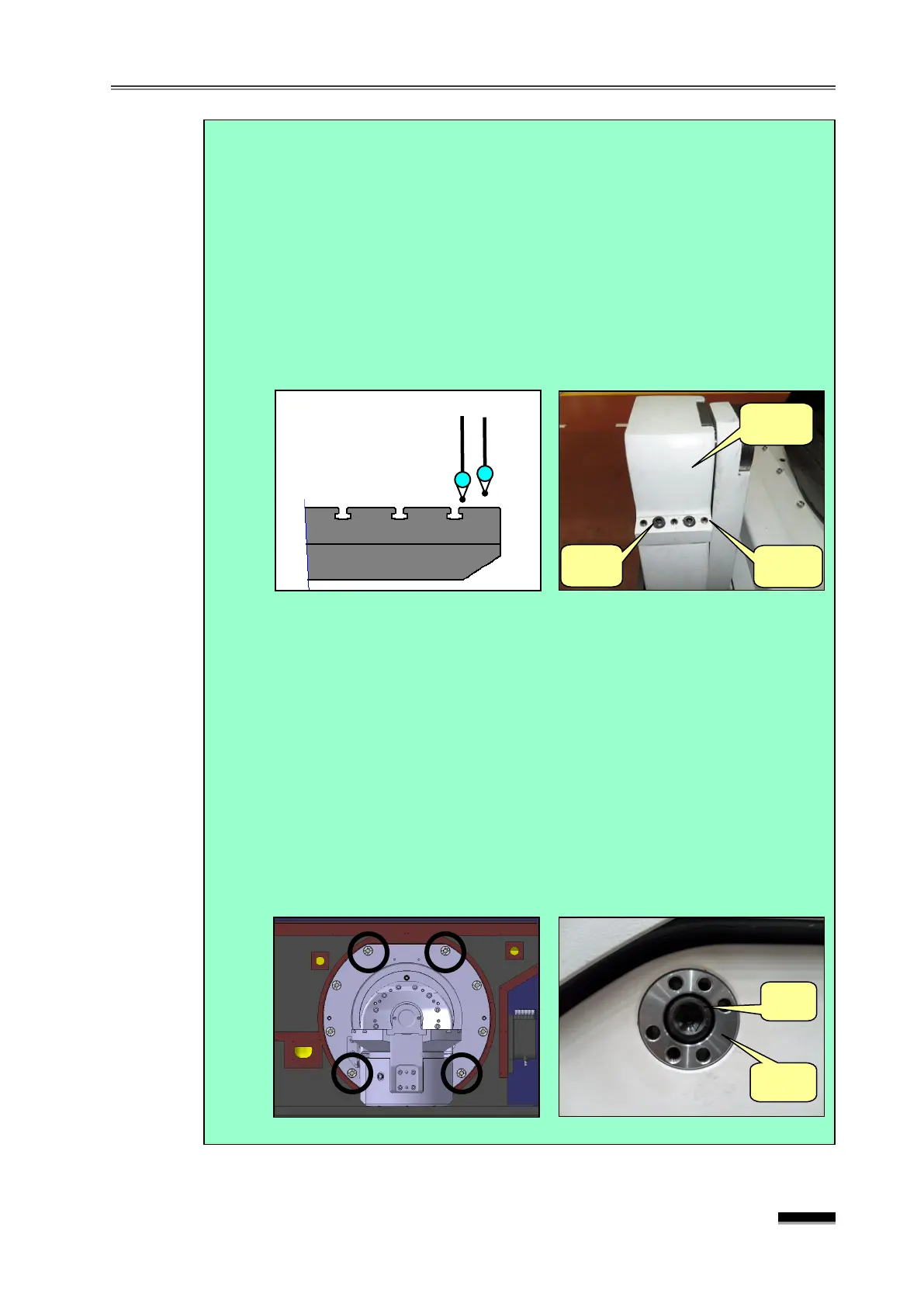
(2) Set up two indicators on the spindle head, perform “0” setting while
touching the needle on the -groove side on the table end and table top,
and then loosen the 160601-02056C Bearing Body Fixing Bolts (4- BB8
ⅹ45) and Adjust Bolts (6-120106-01192).
▪ Loosen them so that the Bearing Body is not affected at all and moves
on its own.
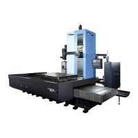
(3) Loosen the four remaining bolts (except for the two top and two bottom
bolts) of the eight (8) table fixing bolts, slightly loosen the two upper side
fixing bolts if the front side is “+ ” in measurement of table top parallelism
(the two lower side bolts if it is “-”), turn them to the right little by little with
the Adjust Block Adjustment Hook Wrench until the indicator on the table
top moves by about 1.5 times the measurement of the initial table top
parallelism while the indicator on the T-groove side does not move.
▪ If the Adjust Block Adjustment Hook Wrench has not been prepared,
use a rod to turn it by inserting a bolt into the tap hole machined in the
Adjust Block.