68
6. Machine Accuracy Measurement and Adjustment
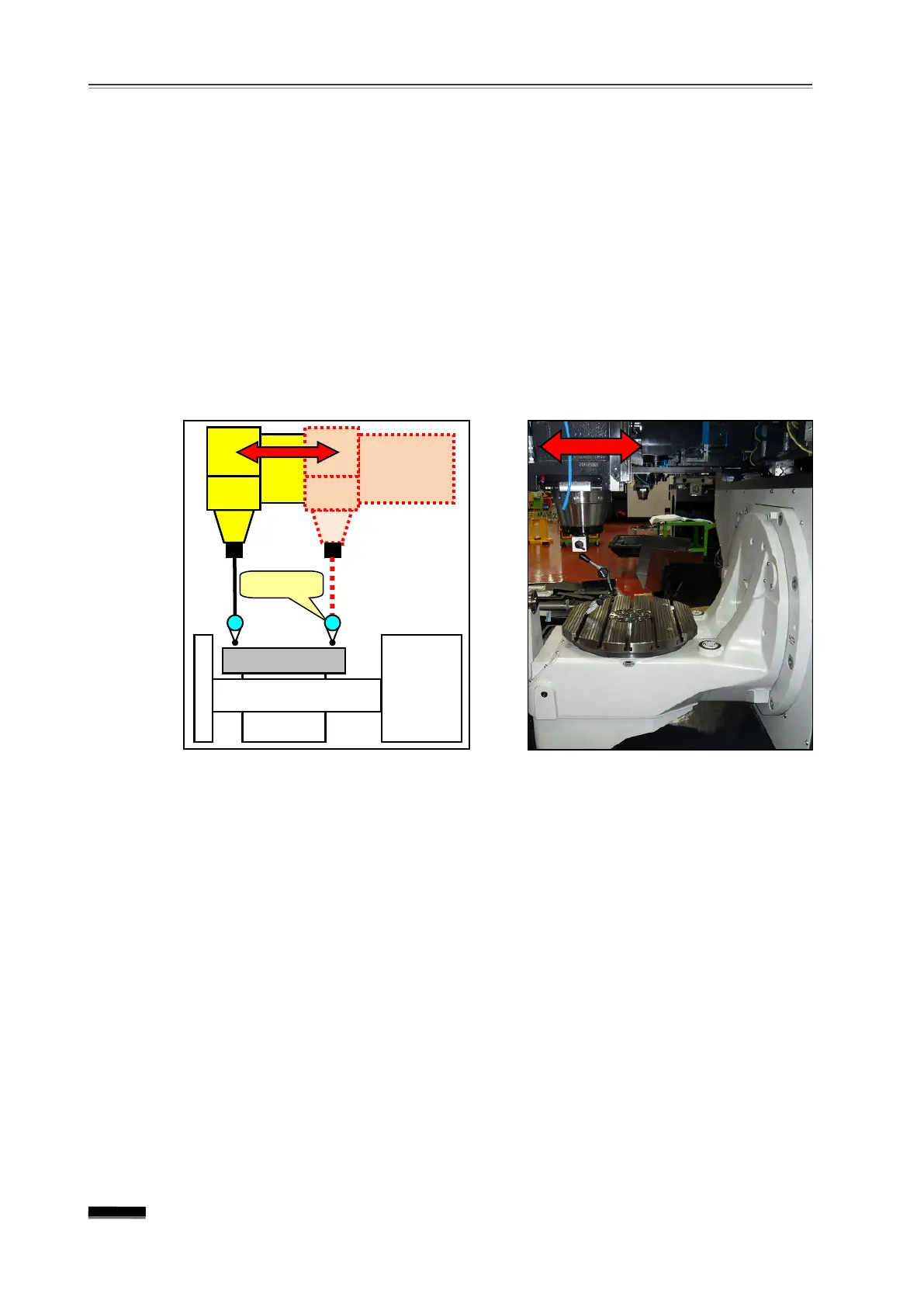
6.12 Table top and Y-axis feed parallelism
① After setting up an indicator on the spindle, transfer the T-axis to -150.
② Perform “0 ” setting on the indicator set up to the spindle at a table surface about
150mm away from the table center in the Y-axis “ -” direction.
③ Move the Y-axis about 300mm in the “+ ”
direction and measure the error amount o
the indicator.
▶ Measurement position : Height of the same table top of Y-150. and Y150. po
▶ Tolerance : 0.010mm / 300mm
Since the L/M Guide is assembled in the spindle head body, it is highly unlikely that the
table top and X-axis feed parallelism will go wrong. However, in the event of accuracy,
check the following accuracies related and review the error amount and direction before
making the necessary corrections.
① 6.10 C-axis centerline and Y-axis movement squareness
②
6.16 Table top run-out
③
6.8 Spindle centerline and Y-axis movement squareness
If there is no irregularity in
“② 6.16 Table top run-out” as mentioned above, adjust
accuracy by adjusting the Table Ass’y locking device.