71
6. Machine Accuracy Measurement and Adjustment
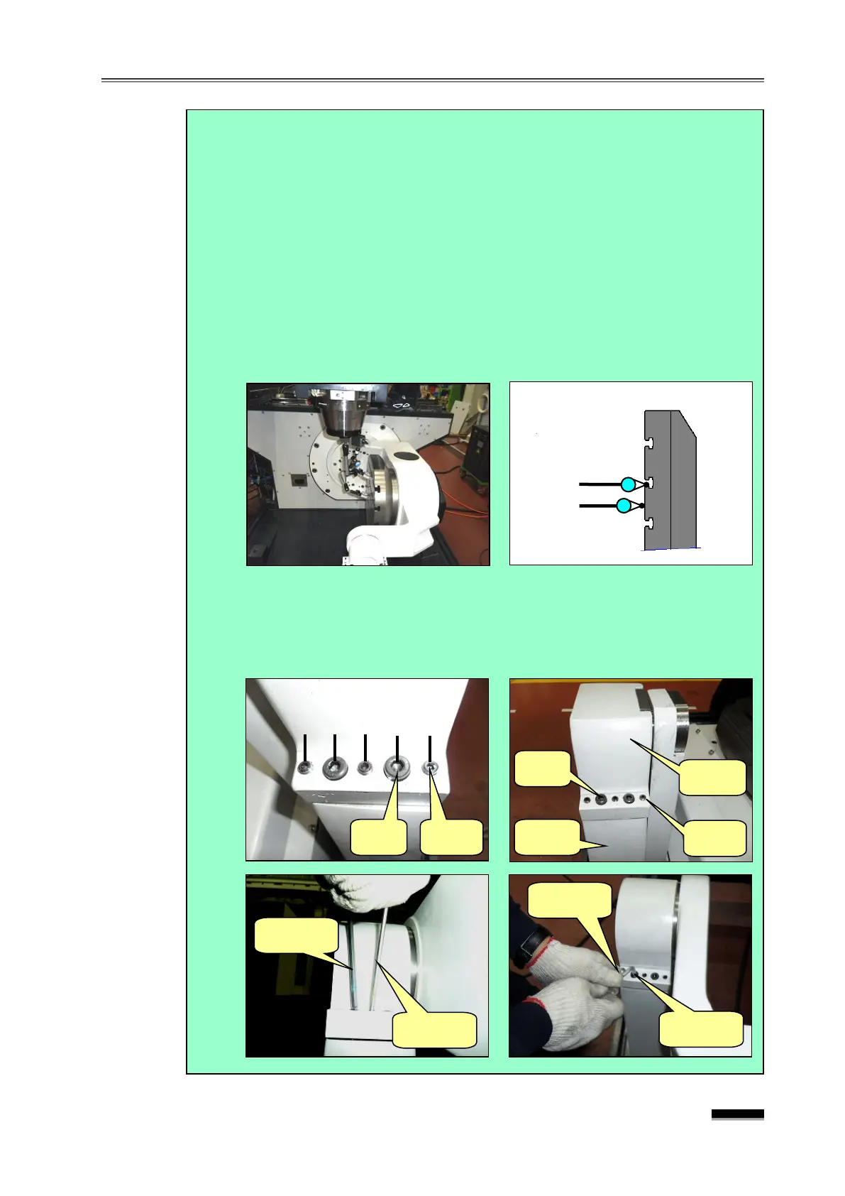
(6) Set up two indicators on the spindle head, perform “0” setting while the
needle makes contact with the T-groove side of the table end and table
top, and then secure the bearing body.
① Lock the Adjust Bolts (6ea) carefully to make contact with the 160601-
02058C Support Body.
② While checking the indicator installed on the table, tighten the Adjust
Bolt and fixing bolt alternately so that a condition is reached whereby
the 6 adjust bolts are pushed with equal force to strongly tighten the
fixing bolts, with the indicator needle remaining unchanged.
③ Again, check the B-axis in paragraph (7) to see if the value is within the
tolerance by measuring the table top and Y-axis parallelism at B0. and B90.
(7) Hold the 5mm and 6mm L-Wrenches at the same time. First, slightly
tighten them at the same time in the order of ②-③, ③-④, ①-②, ④-⑤ to
make sure that the indicator needle does not move. Then, strongly
tighten using the same method while holding the long side.