74
6. Machine Accuracy Measurement and Adjustment
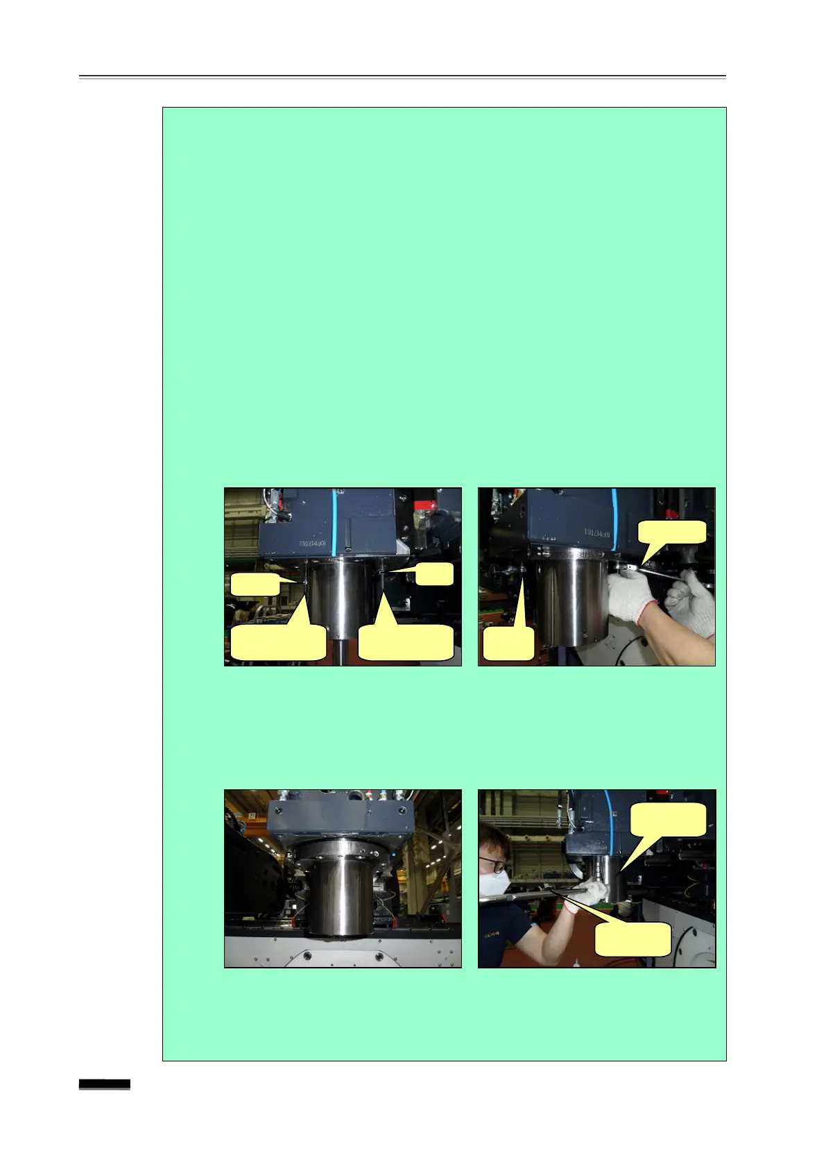
④ Loosen two bolts diagonally from among the Bearing Housing Fixing
Bolts (6-BB10ⅹ45), insert two M10 full thread screws into each M10 Nut
and insert them into the positions from which the fixing bolts have been
removed diagonally, place one nut at a point 40mm away from the
housing entrance, with the other positioned very close to the entrance,
and then loosen all other fixing bolts that have not been disassembled.
▪ One is a safety device designed to prevent the spindle cartridge
from falling when all of the bearing housing fixing bolts have been
loosened, and the other is used when slowly lowering the spindle
cartridge downwards.
⑤ Using a spanner to rotate the nut which makes contact with the
bearing housing, lower the spindle cartridge to the position where the
adjusting liner can be taken out.
▪ Due to its own weight, the Spindle Cartridge falls naturally. While
being lowered, check whether various sensor cables, air tubes, etc.
on the upper side are being pulled.
(3) Take out the following liner, polish as calculated, reassemble and tighten
the fixing bolts accordingly: Left liner if the bottom is tilted to the right in
the Test-Bar X-Z measurement; right liner if tilted to the left in the X-Z
measurement; Front liner if tilted to the rear in the Y-Z measurement;
Rear liner if tilted to the front in the Y-Z measurement.
(4) Reassemble the Tubes, Connector, Hoses, Fitting Cover, etc.
(5) Reassemble the Bearing Housing, measure the squareness and repeat
until the result is satisfactory.