11
Assembly and Installation
Assembly and Installation
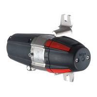
The gas transmitter installation may only be carried out by competent personnel (e.g. Dräger
Safety service personnel) under observation of the regulations applicable at the respective
location.
Assembly
— Select the mounting location to achieve the maximum detection effect.
Free air circulation around the gas transmitter must not be hampered.
— The mounting location of the gas transmitter must be selected as near as possible to the
location of the possible leakage place:
— Local air flow conditions must be considered. Install the gas transmitter at the location at
which you can expect the highest gas concentration.
— Install the gas transmitter in a position where there is the lowest risk of mechanical damage.
— The gas transmitter must be sufficiently accessible for maintenance. Observe a clearance
of approx. 20 cm (7.9 inch) around the gas transmitter!
Please observe the preferred orientation
— If a splash guard (part no. 68 11 911 or 68 11 912) is used then take care during assembly
to ensure that the status indicator lights are in a vertical line. The "Dräger" writing of the
splash guard must be able to be read horizontally. A maximum deviation of ±30
o
from the
horizontal position is permissible.
— Another assembly method is only permissible for gas transmitters without splash guard,
e.g. for applications in ducts – this increases the risk of contamination of the optical
surfaces.
— to monitor gases or vapours that are lighter than air, the gas transmitter should be
installed above the possible leakage place.
— to monitor gases or vapours that are heavier than air, the gas transmitter should be
installed as near to the ground as possible.
NOTICE
Water and/or dirt on the optical surface areas may trip a warning or fault.
 Loading...
