31
Accessories
Status Indicator PIR 7000 / 7200
(Part no. 68 11 625 / 68 11 920)
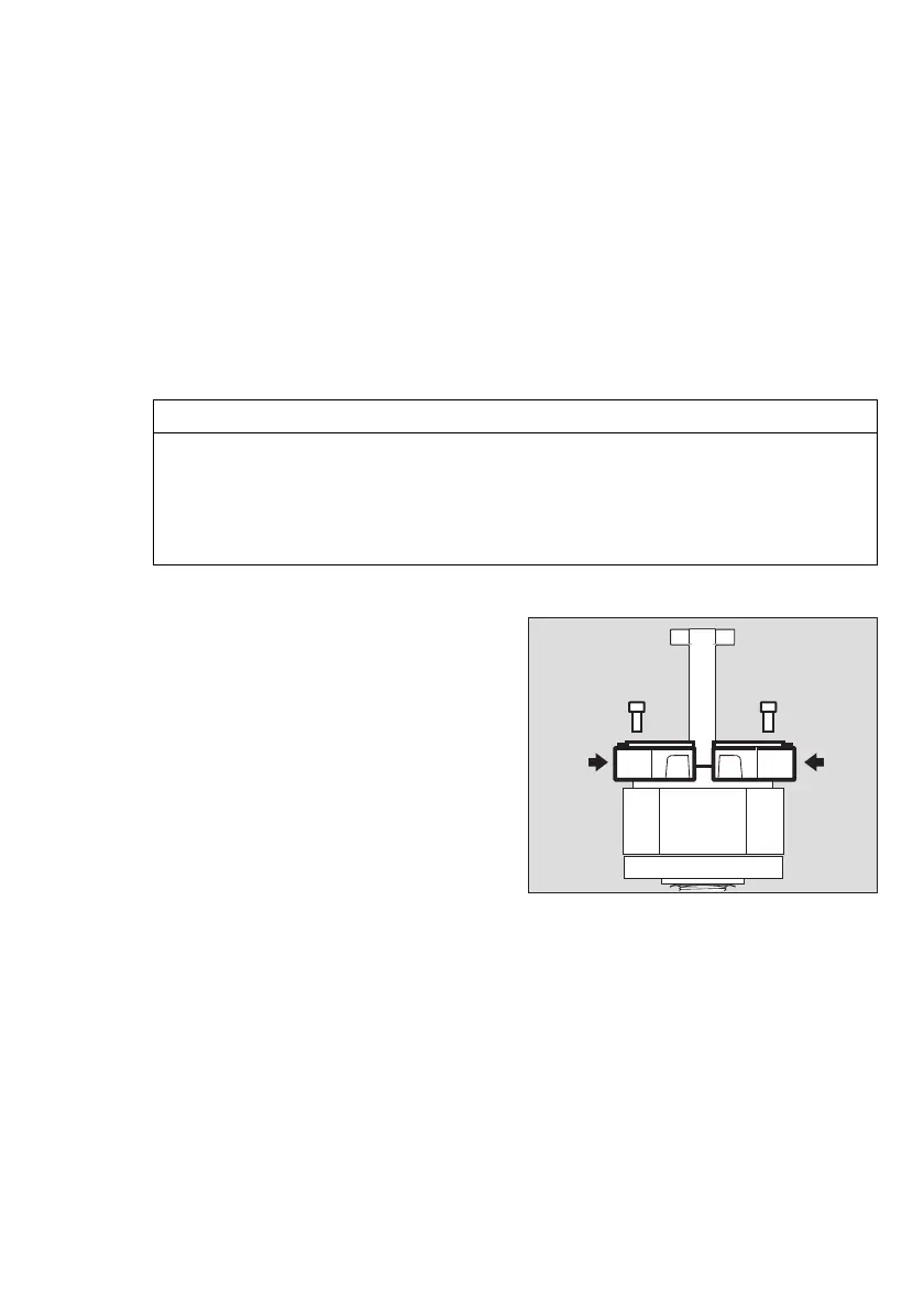
Mounting:
For mounting on a gas transmitter with
mounting set PIR 7000 (part no. 6811648):
● Clean sealing surfaces on the gas
transmitter, if required. Always allow the
sealing surfaces and the base of the
measuring cuvette to dry completely.
● Place the two parts of the status display
on the gas transmitter and connect
together.
Make sure that no seals are jammed.
● Tighten the two screws.
For mounting on a gas transmitter without
mounting set PIR 7000:
● Mount the joint ring PIR 7000 (included
with the status indicator) before mounting
the status indicator.
Intended use:
The status indicator contains light-conducting components for transmitting light signals to the
outer edge of the status indicator.
The gas transmitter features two status lights and provides the following information:
— Continuous green for indicating operational readiness
— Continuous yellow for displaying a fault or a warning
— Continuous yellow for displaying an error or a warning.
These light signals are arranged on two opposing sides of the status display.
NOTICE
The positioning of the light signals in relation to the upper side/underside of the gas
transmitter may change dependent on how the gas transmitter is mounted. Basically, the
colour assignment (yellow/green) is decisive, not the position of the light signals on the
status indicator.
Dräger Safety recommends that the labels (Power/Fault) are affixed in a such a way that the
outlet areas of the light signals are identified unambiguously.
01823886_01.eps

 Loading...


