16
Assembly and Installation
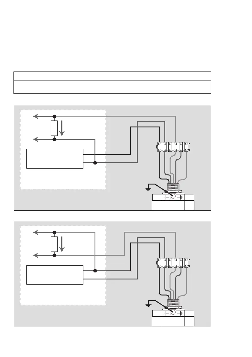
Current Source / Current Sink Operation
— The 4 to 20 mA signal output of the gas transmitter Dräger PIR 7000 / Dräger PIR 7200
can be switched both as current source (source operation) or as current sink (sink
operation). The gas transmitter detects whether the loop resistance is connected to (+) or
(–) and then automatically switches into current source operation or into current sink
operation.
Connection diagram for operation as 4 to 20 mA current source (source operation):
Connection diagram for operation as 4 to 20 mA current sink (sink operation):
NOTICE
The gas transmitter monitors the signal output current. If the loop resistance R
S
is not
present or is too high, the gas transmitter switches into fault and emits the fault signal.
00423886_01_en.eps
+
+
–
–
R
S
123456
Power supply
red
black
brown
white
green/yellow
Central device, e.g. Dräger REGARD
00523886_01_en.eps
+
+
–
–
R
S
123456
Power supply
red
black
brown
white
green/yellow
Central device, e.g. Dräger REGARD

 Loading...


