15
Assembly and Installation
● If the HART
®
communication is used, observe the corresponding manufacturer
specifications (only valid for devices with integrated HART
®
interface).
● Electrically connect the gas transmitter to the external equipotential bonding.
● Connect the gas transmitter.
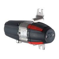
Pin-out Dräger PIR 7000 / Dräger PIR 7200
Colour code of connection leads to gas transmitter and terminal number for factory-mounted
junction box Ex e PIR 7000:
● Check the electrical installation to ensure that all conductors have been correctly
connected.
● Do not shorten the white connection lead when the serial interface is not in use except
where corresponding terminals are available in the junction box. In this case, shorten the
white connection lead and connect it to a free terminal. Make sure that unused conductors
will not contact any part of the housing or other conductors.
● Secure the connection leads within the junction box mechanically.
If the installation has been laid within protective conduits:
● Cast the protective conduit sealings and allow them to harden.
Shielding
When connecting to central device only
(recommended):
● Isolate or shorten shielding in the junction
box to make sure any short circuits are
avoided.
● Connect the gas transmitter electrically to
the external equipotential bonding
conductor (M5 screw – provided with the
gas transmitter).
When connecting to central device and to
gas transmitter (may be required e.g. in
HART
®
operation):
● Connect shielding to internal equipotential
bonding of gas transmitter. Isolate shielding
such that no short circuits can be
generated.
● Connect shielding to earth of central device
(e.g. housing, earth bar, etc.).
External equipotential bonding
Internal equipotential bonding
1 red = + (DC supply 9 to 30 V DC,
and/or 13 to 30 V DC for HART
®
operation;
power consumption max. 7 W)
2 black = – (common reference potential)
4 brown = 4 to 20 mA and HART
®
signal output
5 white = Serial interface
6 green/yellow = Internal equipotential bonding
–connection, external = External equipotential bonding
00223886_01.eps
M5
00323886_01_en.eps
green/yellowshielding
 Loading...
