47
Operational Characteristics
Status Indication
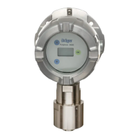
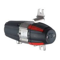
The Dräger PIR 7000 / Dräger PIR 7200 gas transmitter has a green and a yellow status light,
which is brought out to two opposite sides of the gas transmitter by means of the status
indicator, flowcell or bump test adapter. The status lights are always visible from two sides.
Beam Block Warning (patented by Dräger Safety)
Although the gas transmitter Dräger PIR 7000 / Dräger PIR 7200 is equipped with effective
facilities to protect the optic, in rugged environments the beam path may be subject to
contamination over time. In order to prevent interruptions of normal operation caused by heavy
contamination, a concept has been implemented which provides early warning of impending
contamination in the beam path in order to avoid immediate stop of normal operation. For this
purpose, the beam block warning can be activated.
In case the light intensity at the input of the optical measurement module falls below a critical
value due to increasing contamination so that the stability of the measurement signal can no
longer be guaranteed, the gas transmitter outputs a constant current of factory-preset 2 mA at
the analogue interface in case the beam block warning has been activated (configurable
between 0.7 and 3.6 mA). Since the remaining light intensity is still sufficiently high to ensure
a safe detection of alarm states above 15 %LEL (Dräger PIR 7000) or above 15 % of measu-
ring range/15 FSD (Dräger PIR 7200), measurement of the current gas concentration conti-
nues in the background.
State Sample Meaning
After power up
Green/yellow flashing
alternately
Internal self-testing and test of
status lights
Warm-up
Yellow flashes
approx. 1 minute
Warm-up phase after power up
Operational
characteristics
Green on Device operates fault-free
(operation/power)
Fault
Yellow on Fault: See “Faults, Cause and
Remedy” on page 66.
Calibration
Various patterns See “Calibration” on page 54.
NOTICE
Due to the flexible mounting of the gas transmitter, the status lights are not allocated to the
label (Power/Fault) of the status indicator, the flowcell and the bump test adapter. The colour
of the lights are indicative.
 Loading...
