17
Assembly and Installation
U = voltage output in V of power supply for output current of 0.9 A
Impedance of signal loop: See table on page 20.
Operation with Separation of Power Supply and Signal Lines
For gas transmitter operation with isolated power supply and signal lines to the central device,
the junction box Ex e PIR 7000 (68 11 898) provides an unused terminal (terminal no. 3).
Depending on the operating mode of the current output, a bridge between terminal number 2
and terminal number 3 (source operation) or between terminal number 1 and terminal number
3 (sink operation) should be installed in the junction box.
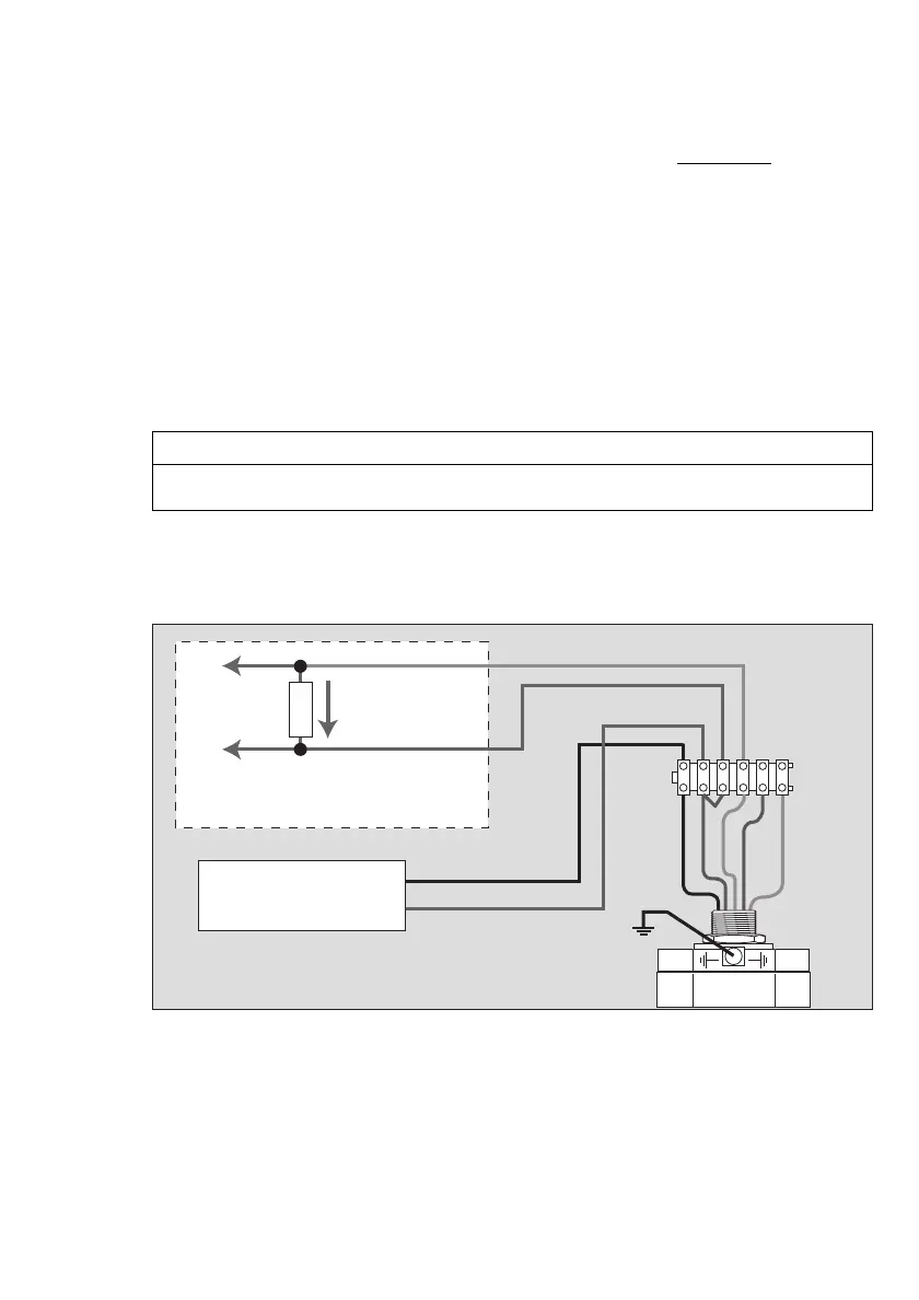
Connection diagram for operation as 4 to 20 mA current source (source operation) with
isolated power supply and signal lines to the central device:
Maximum permissible cable resistance of the
supply line:
R
Cable
(per core) <
U – 9
Ω
1.8
NOTICE
You have to use identical conductors of the same diameter and type for multi-wire
connection. Maximally two conductors per terminal (see page 13).
04123886_01_en.eps
+
+
–
–
R
S
123456
Power supply
red
black
brown
white
green/yellow
Central device

 Loading...


