20
Assembly and Installation
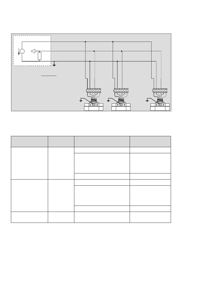
Multidrop installation with HART
®
communication and a (central) power supply:
Impedance Range of Signal Loop
Operating mode Figure Impedance range of signal
loop
1)
1)
The impedance is the addition of the loop resistance R
S
and the line resistance R
cable
of the signal loop.
Range of supply
voltage
Operation without
HART
®
communica-
tion
Figure 1
page 21
0 to 80 Ω at 9 V DC
linear rise with supply voltage
from:
0 to 80 Ω at 9 V to
0 to 500 Ω at 18 V
9 to 18 V DC
0 to 500 Ω 18 to 30 V DC
Operation with
HART
®
communica-
tion (HART
®
opera-
tion)
Figure 2
page 21
230 to 270 Ω at 13 V DC
linear rise with supply voltage
from:
230 to 270 Ω at 13 V to
230 to 500 Ω at 18 V
13 to 18 V DC
230 to 500 Ω 18 to 30 V DC
HART
®
multidrop
operation
Figure 3
page 22
230 to 500 Ω 9 to 30 V DC
00923886_01_en.eps
+
–
R
S
U
R
S
= 230 ... 500 Ω
n = actual number of gas transmitters at
the power supply
U = voltage output in V of power supply
for output current of 0.9 A
R
cable
(per core) < Ω
U
– 9 V
n
x
1.8
. . . . . . . . . . . . . .
123456
123456
123456
12 8
brown
red
black
brown
red
black
brown
red
black

 Loading...


