21
Assembly and Installation
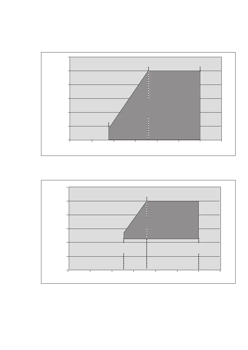
Figure 1:
Range of permissible signal loop impedance for devices operating without HART
®
communication, depending on supply voltage
Figure 2:
Range of permissible signal loop impedance for devices operating with HART
®
communication (HART
®
operation) depending on supply voltage
03823886_01_de.eps
Versorgungsspannung an den Klemmen des Gastransmitters [V]
Impedanz [Ω]
50
0
100
200
300
400
500
600
10
min. 0 Ω bei 18 V
max. 500 Ω bei 18 V
zulässiger Impedanzbereich der
Signalschleife im Betrieb
ohne HART
®
Kommunikation
min. 0 Ω bei 30 V
max. 500 Ω bei 30 V
15 20 25 30 35
min. 0 Ω bei 9 V
max. 80 Ω bei 9 V
03823886_01_en.eps
supply voltage at the terminals of the gas transmitter [V]
loop resistance [Ω]
50
0
100
200
300
400
500
600
10
min. 0 Ω at 18 V
max. 500 Ω at 18 V
permissible impedance range
of the signal loop in operation
without HART communication
min. 0 Ω at 30 V
max. 500 Ω at 30 V
15 20 25 30 35
min. 0 Ω at 9 V
max. 80 Ω at 9 V
03923886_01_en.eps
supply voltage at the terminals of the gas transmitter [V]
loop resistance [Ω]
50
0
100
200
300
400
500
600
10
min. 230 Ω at 18 V
max. 500 Ω at 18 V
min. 230 Ω at 30 V
max. 500 Ω at 30 V
min. 230 Ω at 13 V
max. 270 Ω at 13 V
15 20 25 30 35
permissible impedance range of the
signal loop during HART operation

 Loading...


