66
Faults, Cause and Remedy
Faults, Cause and Remedy
Remedy:
● Disassemble splash guard, check optical surfaces (mirror, window) for contamination and
clean if required, see “Check the Measuring Cuvette of the Gas Transmitter and Clean if
Required” on page 53.
● Calibrate zero-point, see “Zero-Point Calibration Dräger PIR 7000 / Dräger PIR 7200” on
page 57.
● Mount splash guard.
If the error persists:
● Check output circuit (load resistance) and power supply.
If the fault can not be rectified with these measures, the error is often a serious one. You can
use the Dräger CC-Vision GDS software to read out a detailed fault information.
● To do so, connect the gas transmitter via HART
®
or the serial interface with the PC (see
page 63).
● Start Dräger CC-Vision GDS Software and read out the errors/error code.
● Contact Dräger Safety, if necessary.
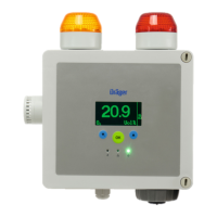
The yellow status light signals errors or
faults of the gas transmitter. It is irrelevant
which error/fault has occurred. The current
output in the factory pre-set configuration is
<1.2 mA.
An output signal of 0 mA indicates an error
in the current loop or a defective device.
● Check current loop.
03623886_01.eps
 Loading...
