51
Operational Characteristics
Normal Operation
Configuration of the 4 to 20 mA Signal Output
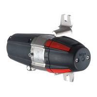
The gas transmitter generates a 4 to 20 mA signal, proportional to the measured gas
concentration, when the gas transmitter is configured for analogue signal transmission.
For the digital processing of gas transmitter data you can use:
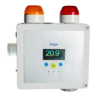
— Dräger REGARD HART
®
-channel card (part no. 42 05 900), installed in a REGARD
control system (Software Version 1.2 Polytron IR)
or
— any HART
®
communication tool interpreting the HART
®
commands selected for the
Dräger PIR 7000 / Dräger PIR 7200
or
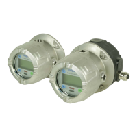
— Operating and display unit Dräger PEX 3300 / PEX 7300.
The gas transmitter periodically runs self tests for numerous internal functions. The gas
transmitter outputs a fault signal as soon as a deviation from normal operation is detected.
Current Meaning Configurable
(0.7...3.6 mA)
Factory
setting
4 mA Zero-point No – – –
20 mA Full-scale deflection No – – –
<1.2 mA Fault, non-latching Yes – – –
3.8 mA ... 4 mA Under-range No – – –
20 mA ... 20.5 mA Full-scale deflection exceeded
(over-range)
No – – –
3 mA Maintenance signal Yes – – –
2 mA Beam block warning
(preventive maintenance function)
Yes Inactive
<1.2 mA Device in HART
®
multidrop operation
(polling address 1 ... 15)
No Disabled
CAUTION
Gas transmitters with splash guard must be regularly checked for contamination of the
splash guard. Any contamination may cause an increase of the measured value response
time.
In case of contamination: Clean splash guard, replace if necessary.
 Loading...
