19
Assembly and Installation
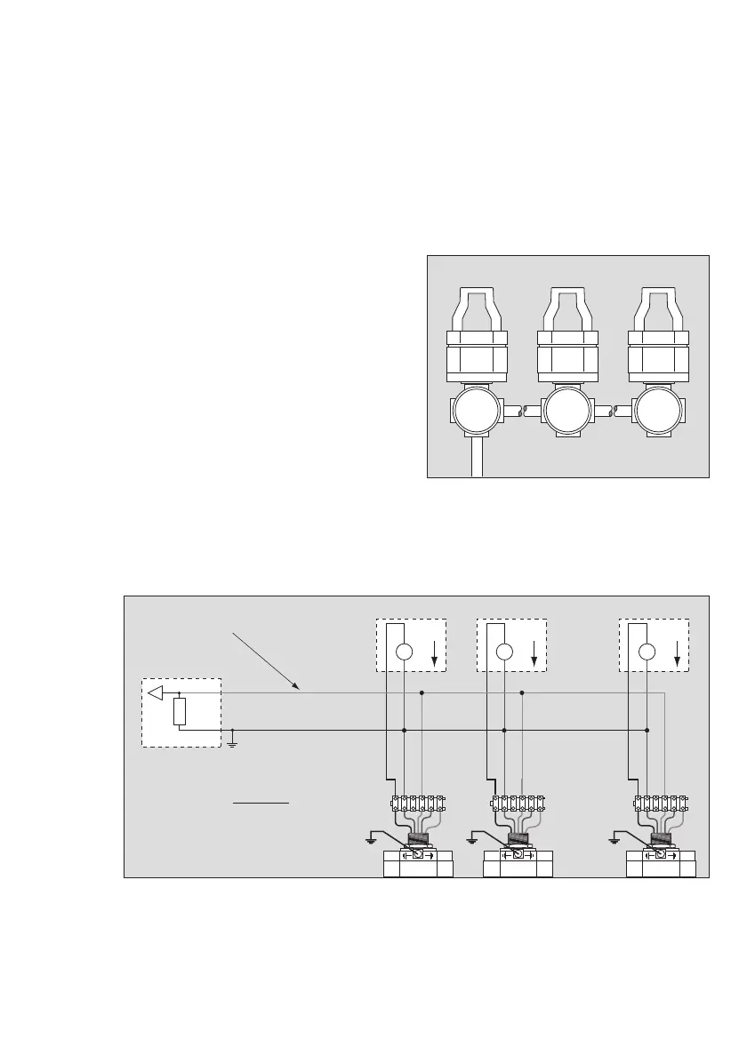
Connection between Several Gas Transmitters and Multidrop-capable HART
®
Central
Device
● Each gas transmitter must first be put into operation separately.
All gas transmitters which are scheduled for a multidrop line should be configured using a
different "Polling Address" in the range from "1" to "15". It is best to assign sequential
polling addresses, starting with "1".
● Configuration of "Polling Address": See Instructions for Use of the Dräger CC-Vision GDS
software.
Connection diagrams:
Multidrop installation with HART
®
communication and isolated power supply units:
● Depending on the power supply, up to a
maximum of 8 gas transmitters can be
connected to a multidrop line.
00723886_01.eps
00823886_01_en.eps
+
–
R
S
+
–
UU
+
–
U
black
brown
red
black
brown
red
black
brown
red
R
S
+ R
cable
< 500 Ω
U = voltage output in V of power supply
with an output current of 0.9 A – R
S
.
R
cable
(per core) < Ω
U
– 9 V
1.8
. . . . . . . . . . . . . .
123456
123456
123456
12 8

 Loading...


