32
Accessories
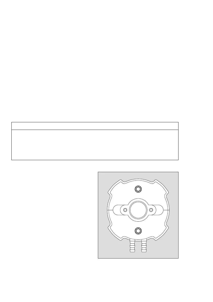
Flowcell PIR 7000 / 7200
(Part no. 68 11 490 / 68 11 910)
Intended use:
— The flowcell is designed for testing the function of the gas transmitter with a high test gas
concentration and external test gas supply.
— Dräger Safety recommends a test gas flow of 0.5 to 1.0 L/min.
It is recommended that you monitor the gas flow rate.
— For gas transmitters with or without splash guard.
— The measuring properties of the gas transmitter are affected by the flowcell.
Therefore, after installation or removal of the flowcell, the zero point and sensitivity of the
gas transmitter should be calibrated!
The gas transmitter features two status lights and provides the following information:
— Continuous green for indicating operational readiness
— Continuous yellow for displaying a fault
— Flashing green/yellow for status messages during the calibration procedure.
These light signals are arranged on two opposing sides of the flowcell.
NOTICE
The positioning of the light signals in relation to the upper side/underside of the gas
transmitter may change dependent on how the gas transmitter is mounted. Basically, the
colour assignment (yellow/green) is decisive, not the position of the light signals on the
status indicator.
Dräger Safety recommends that the labels (Power/Fault) are affixed in a such a way that the
outlet areas of the light signals are identified unambiguously.
Mounting:
For gas transmitters with splash guard and
status indicator:
● Remove splash guard together with
status indicator.
Always required:
● Clean sealing surfaces on the gas
transmitter, if required.
Always allow the sealing surfaces and
the base of the measuring cuvette to dry
completely.
● Fasten flowcell to gas transmitter using
the two screws – the connections (two
hose connectors dia. 6.5 mm) should
point downwards.
02023886_01.eps

 Loading...


