12
Assembly and Installation
Mechanical Installation
— The gas transmitter is designed to be directly attached to a junction box.
— For the model with M25 thread (IDS 011x) we recommend using the junction box Ex e
PIR 7000 (EAC 0000, part no. 68 11 898) – assembly: See page 39.
— Furthermore, any approved junction box can be used that has an M25 (Ex e and Ex tD) or
3/4" NPT (Ex d or Explosion Proof and Ex tD) insertion opening (depending on the thread
of the gas transmitter) and connection terminals for at least three conductors (four
conductors when using the serial interface communication) and earth.
— The junction box must be suitable for the mounting location and the application.
— When mounting the junction box and gas transmitter, make sure that the junction box is not
subject to mechanical stress at the location of the connection.
● Close any unused cable entry openings at the junction box using approved plugs.
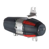
Dräger Safety recommends to use the mounting set PIR 7000 (part no. 68 11 648). The
mounting set is suited for attaching the gas transmitter to level and arched surface areas.
● Assembly: See page 25.
● As an alternative, the joint ring PIR 7000 (part no. 68 11 908) can be used the if the
mounting set is not used, see page 26.
— Sufficient distance to the wall, the ceiling and to the floor is ensured by using the PIR 7000
mounting set.
— In case of other assembly types, make sure that the distance between transmitter and wall,
ceiling or floor is above 4 cm (1.58 inch).
Orientation
The gas transmitter Dräger PIR 7000 / Dräger PIR 7200 is suited for wall, floor and ceiling
assembly.
The mounting set PIR 7000 can be mounted in offset positions of 90
o
, see page 25.
● Loosen the mounting set, rotate it according to the requirements and fasten the screws
again.
NOTICE
On no account should you attempt to open the housing of the gas transmitter!
The device does not contain any parts that can be serviced by the user. Opening of the
device invalidates all guarantee claims.
 Loading...
