13
Assembly and Installation
For connection in the "flameproof enclosure" (Ex d) or "Explosion Proof" type of
explosion protection
● If required: Mount the connecting union approved for the corresponding type of explosion
protection between the junction box and the gas transmitter.
For connection in the "increased safety" (Ex e) type of explosion protection in
conjunction with an approved, commercially available junction box
— The wall thickness of the junction box must be 4.2 mm to 12 mm at the mounting surface.
— The sealing surface towards the gas transmitter must be level and clean in the range from
28 mm to 32 mm diameter in order to ensure a flawless sealing by means of the provided
O-ring.
● Secure the M25 nut against self-loosening.
For connection in the "increased safety" (Ex e) type of explosion protection in conjunc-
tion with the junction box Ex e PIR 7000 (EAC 0000, part no. 68 11 648)
— The junction box Ex e PIR 7000 is designed to be connected to the Dräger PIR 7000 /
Dräger PIR 7200 gas transmitter with M25 threaded connection (IDS 011x). The cable
diameter is between 7 and 12 mm. Cross-section of max. 2.5 mm
2
or 2 x 1 mm
2
may be
connected.
— The torque for the terminal screws is at least 0.6 Nm.
● The cover screws must be tightened with a torque of at least 1.5 Nm (see also page 39).
Installation using the Mounting Set PIR 7000 (68 11 648)
● Make ready the corresponding screw fixing – see "Drilling Template – Mounting Set
PIR 7000" on page 81.
● Securely affix the mounting bracket of the mounting set.
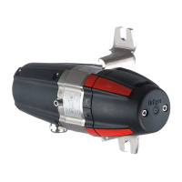
● Mount the gas transmitter to the mounting bracket and secure it with the provided screws
(min. torque 10 Nm).
— Install the gas transmitter so that the status indicator, flowcell or bump test adapter lights
and, if applicable, the process adapter and/or process cuvette status lights are clearly
visible.
 Loading...
