15 | Examples of settings
D-ISC 100 x xx2
173
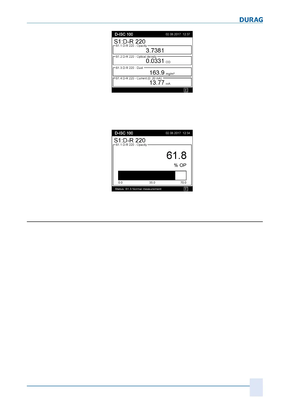
Fig.15.30: Displaying a quad measurement channel
The measured values for the display types "Single" and "Dual"
can display a bar graph
in addition to
the displayed numeric val-
ues. To do this, the option "bar graph" must be selected in the
display menu.
Fig.15.31: Displaying a single measurement channel with bar graph
15.10 Examples: Assignment of the analogue output
(current output)
The D‑ISC100 has
one
(internal) 4…20mA analogue output. Up
to 4 additional expansion modules can be incorporated, each
with 4 analogue outputs. Each current output can be assigned to
one of the four measurement channels for a sensor (module con-
figuration, methodA). The output value of the measurement
channel is output at the assigned current output.
 Loading...