4 | Installation and commissioning
D-ISC 100 x xx2
41
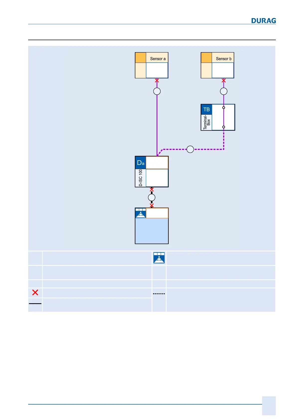
4.2.5 Sensor network bus architecture (one D-ISC 100)
X2
Modbus
Slave
Adr. y
Sa
Modbus
Slave
Adr. z
Sb
Modbus
Master
PLC
P L Crogrammable ogic ontroller
D-EMS 2000
Environmental- and Process Data
Management System
D-ESI 100
D EURAG ngineering and
ervice nterfaceS I
Modbus
Master
Modbus
Slave
X2
Adr. x
X6
A
B
B
B
D
x
D-ISC 100 Central monitoring room
S
x
Sensor
A
Modbus A (Modbus RTU/TCP or analogue/di-
gital interfaces)
TB
Terminal box
B
Modbus B (Modbus RTU)
Bus termination Bus cable
Pre-assembled
cable with connector (max. 12m)
Table4.2: Example system components and their bus connections (one D‑ISC
100)
One D‑ISC100 can control up to 8 different sensors.
In the example above, the D‑ISC100 (Da) supplies sensor Sa
with voltage, and the terminal box (TB) supplies sensor Sb with
voltage.
 Loading...