4 | Installation and commissioning
D-ISC 100 x xx2
31
● Do not use hoses as attachments or supports for other ob-
jects.
● The purge air hose for the sensor is attached to the hose con-
nection on the D‑ISC100 P using a hose clamp.
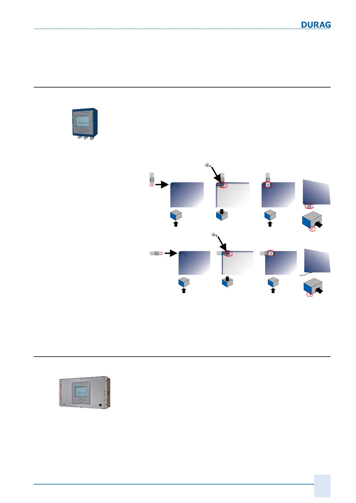
4.1.2 D-ISC 100 C
Standard installation
1.
Firstly screw the four supplied external clips onto the housing.
Depending on the circumstances, the clips can be fitted paral-
lel to the long edge (
A
) and/or parallel to the short edge (
B
) of
the housing (see figures below).
We recommend fitting them to the short edge, as this makes
it easier to access them at a later date when fitted to the wall
(no cables in front of the wall attachment).
Maximum torque when tightening the screws: 10Nm.
2.
Install the Universal control unit onto the wall clips on the wall.
The
installation drawing
can be found in Section 14 Dimen-
sioned drawings [}151].
4.1.3 D-ISC 100 R
Standard installation
The D‑ISC100R version is intended for installation in a 19" rack
(48.26cm).
1.
Start by connecting the D‑ISC100R as necessary.
The relevant Sections are listed below.
2.
Slide the unit into the rack. An installation height of 6 HE [U]
is required.
3.
Secure the D‑ISC100R against falling from the rack by
screwing the side bracket into the rack through the pre-
punched oval holes.
 Loading...