3 | Device and Function description
20
D-ISC 100 x xx2
54
internal
55
internal
56
internal
57
Battery (CR 2032)
58
NC/NO relay switching
81
Ethernet
(for internal
Modbus TCP module)
83
Display unit connection
84
USB port (2x)
X2
DURAG Modbus connection
X3
Analogue/digital out connection
X4
Connection between two meas-
uring heads (pre-wired)
X5
Connection of operating voltage
24V (pre-wired)
X6
Connection of sensor Modbus
(pre-wired)
Table3.8: CPU module
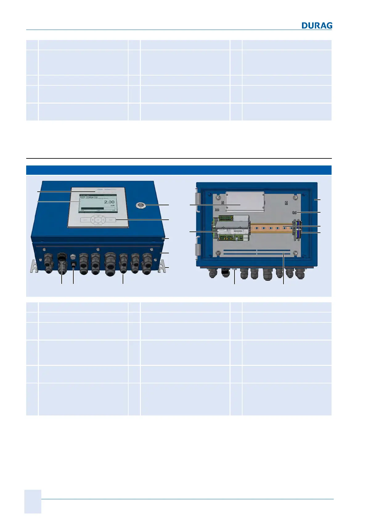
3.3.3 D-ISC 100 M
D-ISC 100 M
30
72
10
20
45
42
43
46
82 84
76
42
X1
61
47
62
48
85
10
Display
20
Keyboard
30
LEDs
42
Lower housing part
43
Housing door
45
Lock
46
Device fastening
47
Top hat rail
48
Rails for
shield terminals
61
Power supply unit
62
Top hat rail module
D‑ISC100CPU module
(3.3.2 CPU module [}19])
72
Cable glands
76
Vent plugs
82
Socket for
2ndmeasuring head
84
USB port
X1
Plug terminals for
device connection
(see Technical data
for operating voltage)
Table3.9: Parts designation D-ISC 100 M
 Loading...