5 | Basic operation of the D-ISC 100
D-ISC 100 x xx2
73
5.
Pressing the
key again generally leads directly back to the
measured value display. You will always be taken back to the
place at which you previously left the measured value display.
Info box message:
Changes on system settings saved successfully]
If you have moved within the settings menu, even
without
making
any changes, you may still receive an info box message
confirming a save action when you leave this menu.
In this case, it is the existing (
unchanged
) settings that have
been saved.
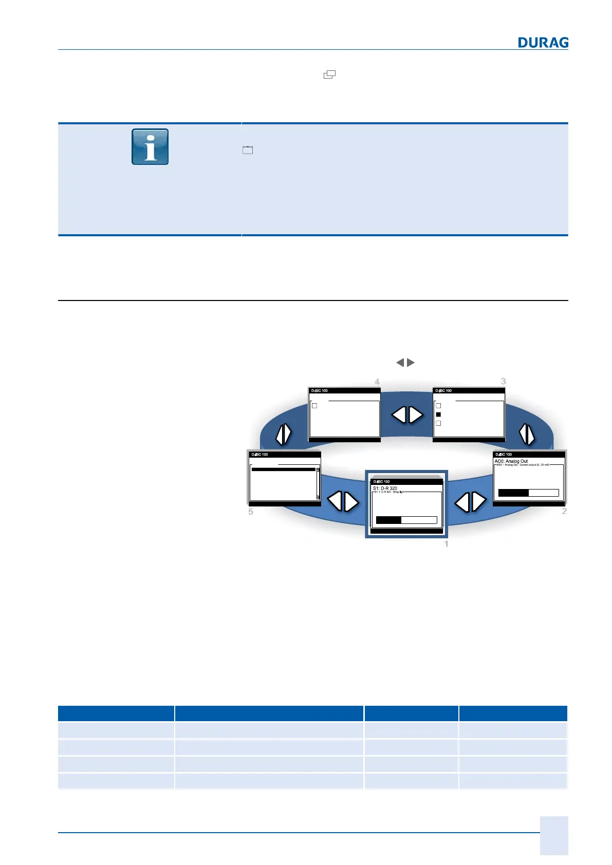
5.3 Measured value and status displays
Depending on the configuration, the D‑ISC100 has several
measured value and status displays, which are arranged in a
loop as shown in the following figure. You can scroll through the
displays using the arrow keys (
).
drw_disc100_Display_0001_S2.png
1
2
34
5
01.04.2013 12:37
Status: S1.1: Normal measurement
10.02
mA
0.00 10.00 20.00
01.04.2013 12:38
Status: S1.1: Normal measurement
D:D-ISC 100
Status of all channels
Normal measurement
Normal measurement
No messages
01.04.2013 12:37
Status: S1.1: Normal measurement
747.5
SL
0.0 1000.0 2000.0
01.04.2013 12:38
Status: S1.1: Maintenance / check function (C)
DO0: Digital Out
DO0: Digital Out
DO0.3 assigned to: S1.1
Maintenance demand (M)
DO0.2 assigned to: S1.1
Maintenance / check function (C)
DO0.1 assigned to: S1.1
Fault (F)
01.04.2013 12:38
Status: S1.1: Normal measurement
DI0: Digital In
DI0: Digital In
DI0.1 not assigned
-
D:
S1.1:
S1.2:
S1.3:
S1.4:
Normal measurement
Normal measurement
Fig.5.9: Measured value and status displays (display loop)
The display settings can be adjusted for the system components
listed below:
Sensors and modules are marked in the screen menu by corres-
ponding abbreviations, which allows them to be easily identified.
If several similar units of these sensors or modules are installed
in/on a Universal control unit the abbreviation is supplemented
by numbers (depending on the component: m, n, o, p).
The following components each have one measured value or
status display:
Component Function Status display Measurement display
D‑ISC100 Universal control unit (D)* X
Sensor divers (Sn)* X
Software module Channel composition (MXo)* X
Software module External devices (SXp)* X
 Loading...