9 | System setup menu 3
D-ISC 100 x xx2
91
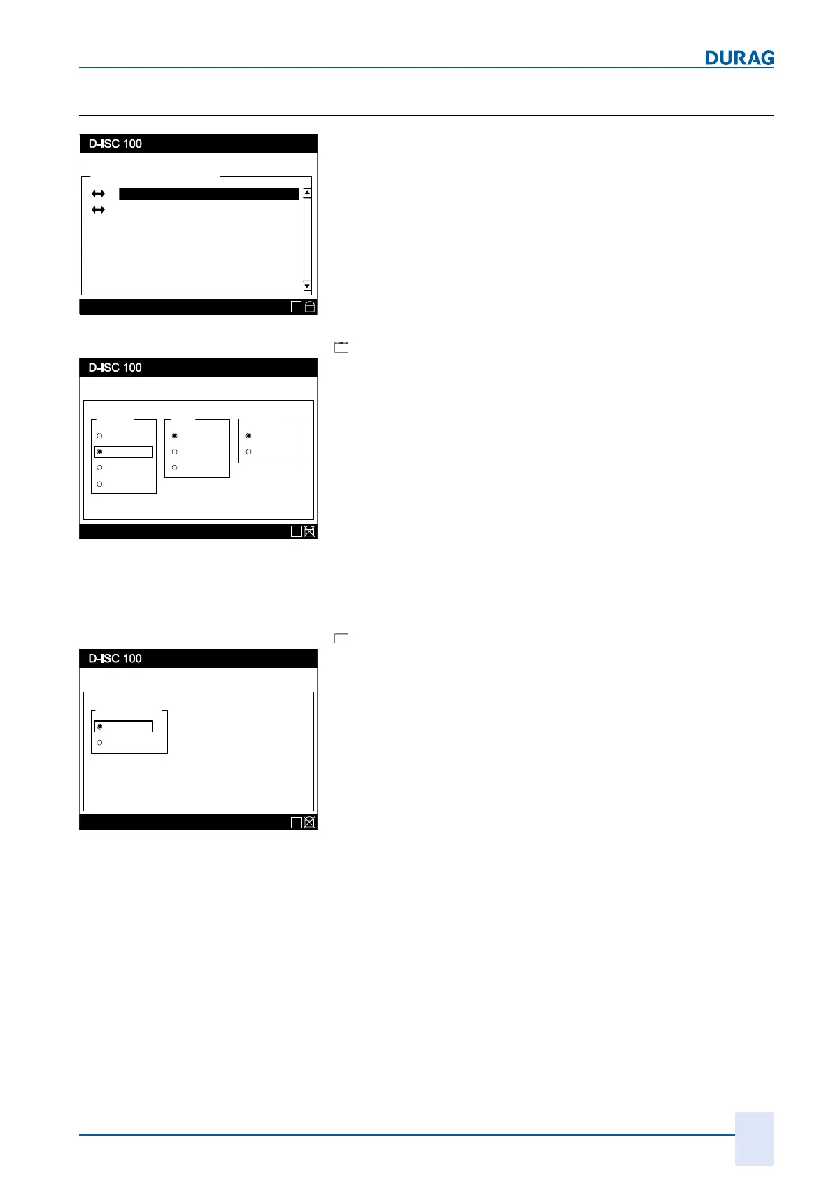
9.3 DURAG Modbus
Menu: 3.3.1
DURAG-Modbus
\\System setup\DURAG-Modbus
Communication parameter
Bus termination
Status: S1.3:Normal measurement
E
Fig.9.4: DURAG Modbus settings
relates to the bus settings.
Communication parameters:
[
Communication parameters:
Menu: 3.3.1
Status: S1.3:Normal measurement
Communication parameter
Baudrate Parity
9600
19200
38400
None
Even
Stop Bits
1 Bit
2 Bits
Odd
57600
E
Fig.9.5: Setup communication parameters
● Set/select the Baud rate, parity and number of stop bits
Parameterise all connected devices with the same settings.
All devices connected to the bus must use the same communica-
tion parameters. If necessary, check the settings of the other
devices beforehand. If a different Baud rate, parity or number of
stop bits is selected, no further data exchange can be performed
between the Universal control unit and that device. If changes
are made to these parameters, all connected devices must there-
fore be parameterised with the same settings.
For the default settings, see 13.4 D-ISC 100 communication set-
tings [}148].
See our 15.3 Example: Setting / checking DURAG the Modbus
[}158] for details of how to set the communication parameters.
Bus termination:
[
Bus−Termination]:
Menu: 3.3.2
Status: S1.3:Normal measurement
Bus parameter
Bus-Termination
Active
Inactive
E
Fig.9.6: Switch the terminating resistor on/off.
● Enabling/Disabling the bus termination
● Terminating DURAG Modbus at both ends. To do so, activate
the termination at the devices at the ends of the bus
Depending on where the Universal control unit - D‑ISC100 is
located within the bus (see also Sections 4.2.5 Sensor network
bus architecture (one D-ISC 100) [}41] and 4.2.6 Sensor network
bus architecture (multiple D-ISC 100) [}43]), a terminating res-
istor can be attached (active).
The DURAG Modbus
must
be terminated at each end. This is
done by activating the termination at the devices at the ends of
the bus If a sensor is connected directly to the D‑ISC100, the
termination is activated at the D‑ISC100
and
at the sensor.
See our 15.3 Example: Setting / checking DURAG the Modbus
[}158] for details of how to switch on the terminating resistor.
 Loading...