4 | Installation and commissioning
D-ISC 100 x xx2
53
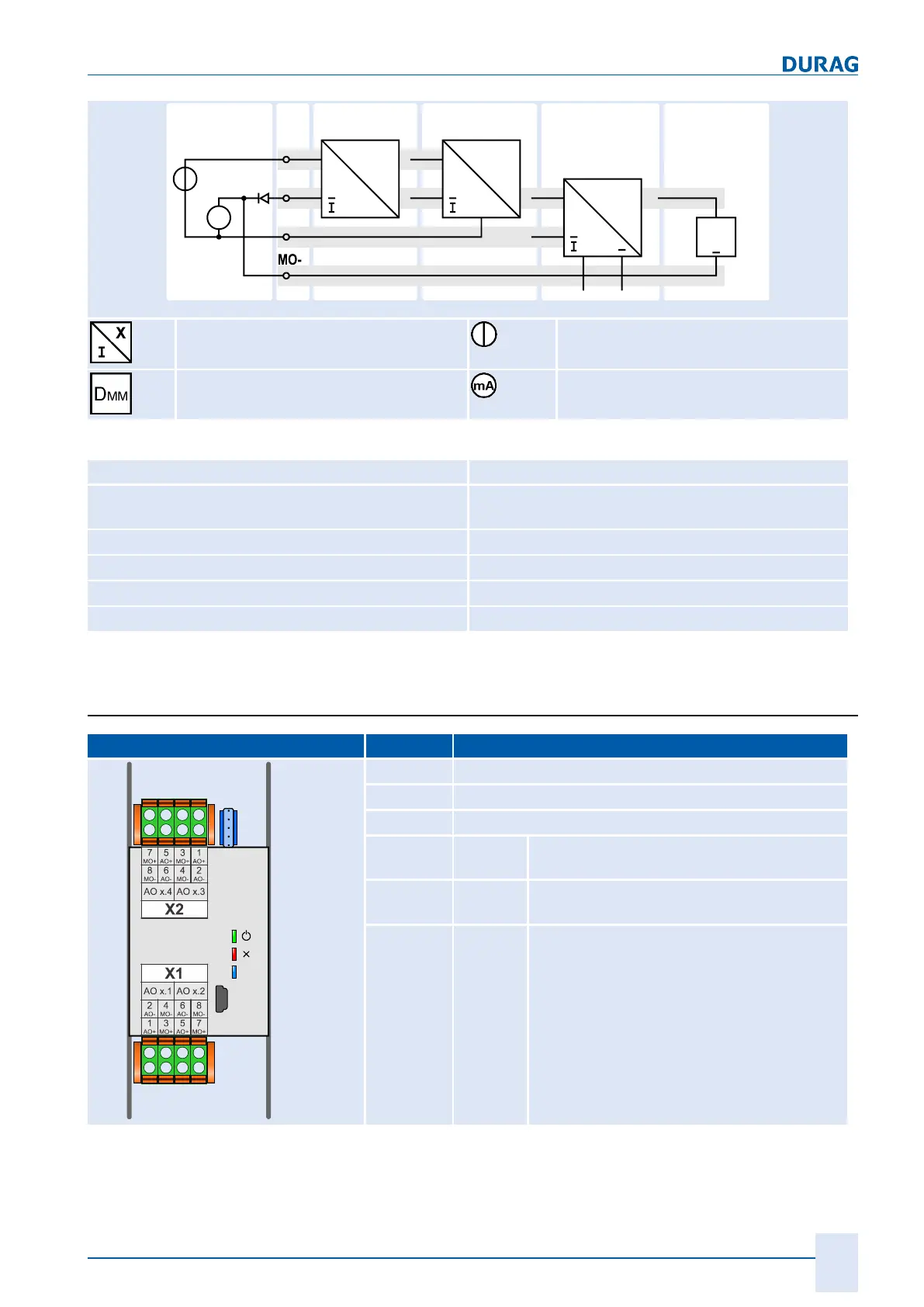
2LT 3LT TEV
15V
AI+
AI-
mA
+
X
mA
out
+
X
mA
out
+
X
mA
out
+
V
in
Monitor
DMM
+
DMM
~ ~
ESB
Measured value converter
with current output
Voltage source
Digital multimeter/monitor Current measurement
Table4.6: Connection of analogue input module
Type Description
ESB Equivalent circuit
for the analogue input expansion module
2LT 2-wire transmitter
3LT 3-wire transmitter
TEV Transmitter with its own power supply
DMM External digital multimeter for test purposes
Table4.7: Plug assignment for the analogue input expansion module, example
AIx.1
4.3.4 Analogue output
Pos Description
X1
Module connecting terminals
X2
Module connecting terminals
X3
Service
LED9
green LED ON when in operation;
FLASHING during communication (internal)
LED10
red LED ON in event of
expansion module fault
LED11
blue LED ON when USB connected
Table4.8: Connecting terminals and LED functions of the analogue output ex-
pansion module
 Loading...