4 | Installation and commissioning
56
D-ISC 100 x xx2
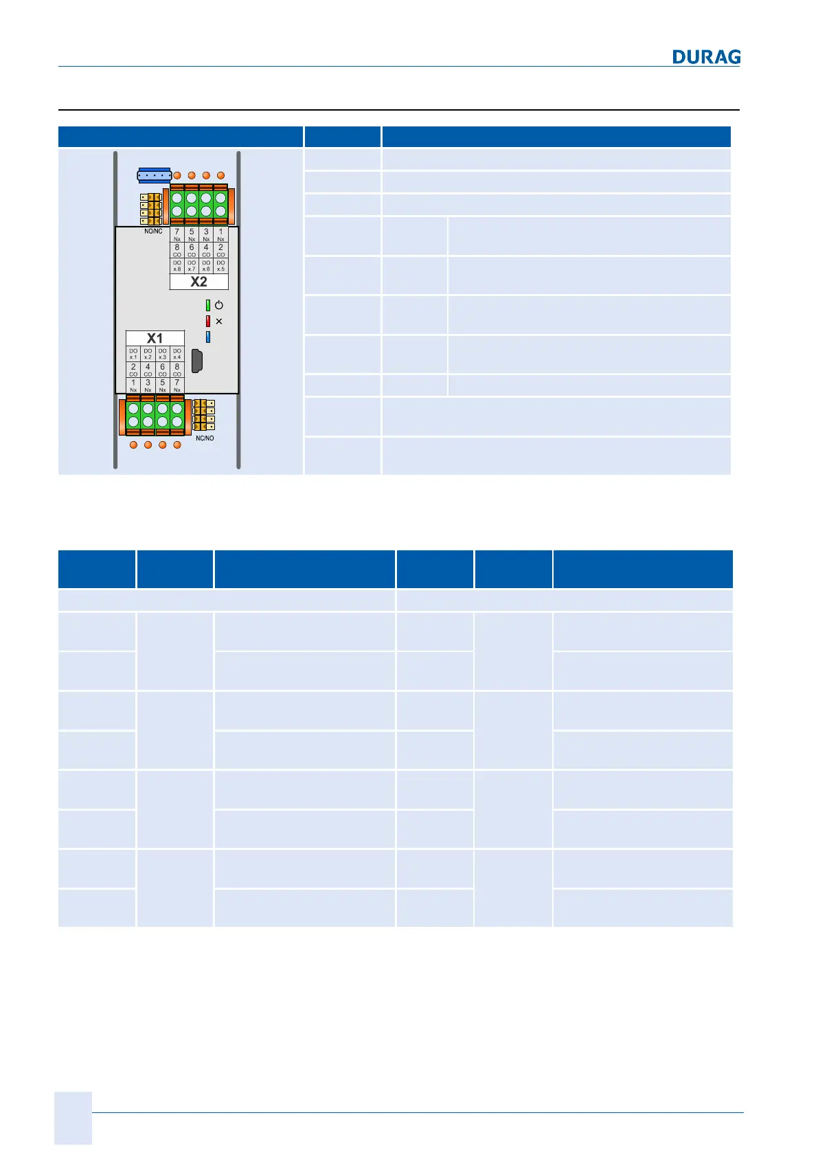
4.3.6 Digital output
Pos Description
LED
LED 9
LED 10
LED 11
LED1 2 3 4
5 6 7 8
SW2.8
SW2.7
SW2.6
SW2.5
SW1.1
SW1.2
SW1.3
SW1.4
X1
Module connecting terminals
X2
Module connecting terminals
X3
Service
LED1−4
orange LED ON when there is voltage at the relay
coil
.
LED5-8
orange LED ON when there is voltage at the relay
coil
.
LED9
green LED ON when in operation;
FLASHING during communication (internal)
LED10
red LED ON in event of
expansion module fault
LED11
blue LED ON when USB connected
SW1.1…4
NO/NC switching for DOx.1…4
shown switch position means NC
SW2.5…8
NO/NC switching for DOx.5…8
shown switch position means NC
Table4.13: Connecting terminals, LED functions and switches for digital output
expansion module
Plug posi-
tion
Description Plug posi-
tion
Description
X1 X2
X1.1 DO x.1 Nx digital output
(Nx≙SW1.1)
X2.1 DO x.5 Nx digital output
(Nx≙SW2.1)
X1.2 CO digital output
(common)
X2.2 CO digital output
(common)
X1.3 DO x.2 Nx digital output
(Nx≙SW1.2)
X2.3 DO x.6 Nx digital output
(Nx≙SW2.2)
X1.4 CO digital output
(common)
X2.4 CO digital output
(common)
X1.5 DO x.3 Nx digital output
(Nx≙SW1.3)
X2.5 DO x.7 Nx digital output
(Nx≙SW2.3)
X1.6 CO digital output
(common)
X2.6 CO digital output
(common)
X1.7 DO x.4 Nx digital output
(Nx≙SW1.4)
X2.7 DO x.8 Nx digital output
(Nx≙SW2.4)
X1.8 CO digital output
(common)
X2.8 CO digital output
(common)
Table4.14: Plug assignment expansion module digital output
 Loading...