4 | Installation and commissioning
D-ISC 100 x xx2
29
4 Installation and commissioning
4.1 Installation
Transport
to the installation location
Suitable lifting devices should be used to load and unload the
packages if necessary.
Avoid rough impacts. If possible, use the original packaging for
transport.
If there are large temperature or humidity fluctuations, condensa-
tion can cause moisture to form within the devices. This can
cause an electric short circuit. Following transportation, do not
put the devices into operation until the inside of the devices has
reached ambient temperature.
Personnel
The D‑ISC100 must only be installed by specialist personnel
(see 2.2 Personnel, qualifications [}11]).
Installation location
The installation location is selected taking into account
● the 13 Technical data [}146],
● the length of the sensor cables that can be connected to the
D‑ISC100 unit,
● the space requirements (14 Dimensioned drawings [}151]).
The Universal control unit must be freely accessible for operation
and maintenance at all times.
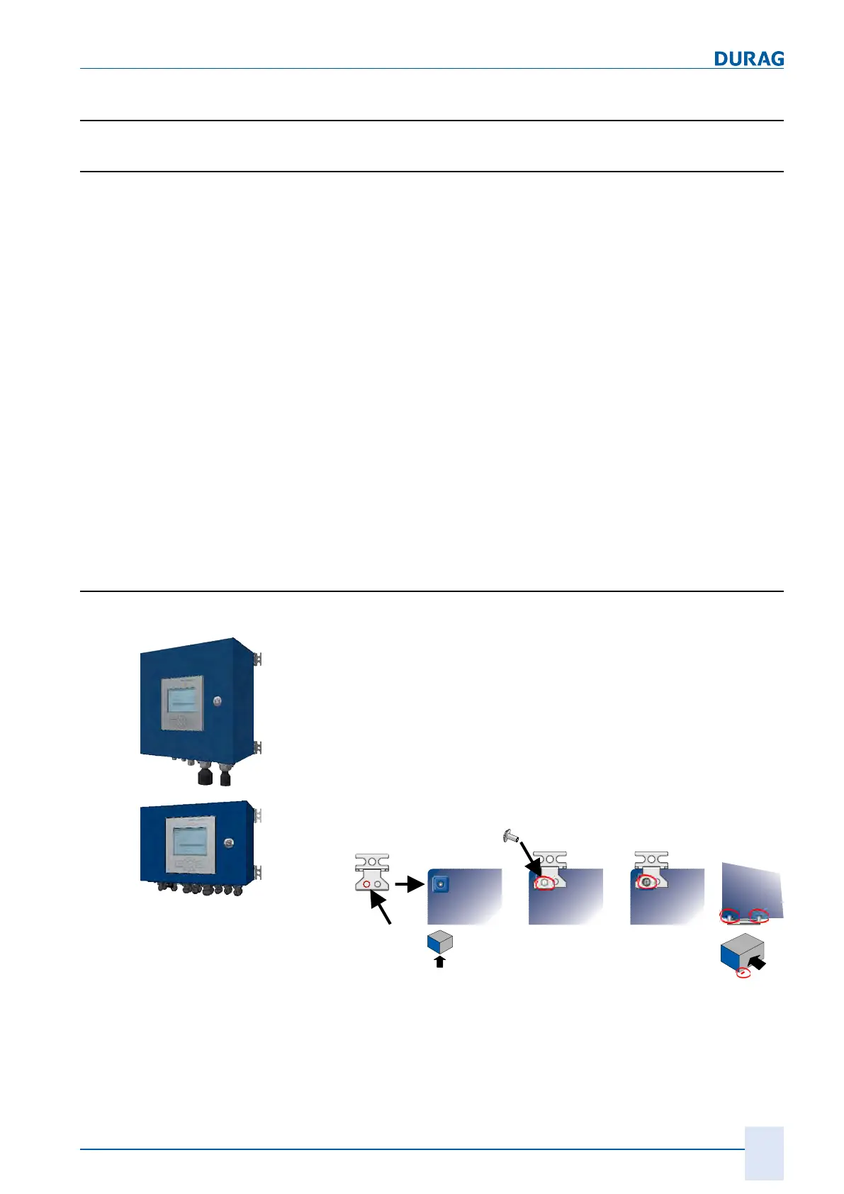
4.1.1 D-ISC 100 P, M
Standard installation
1.
Firstly screw the four supplied external clips onto the housing.
Depending on the circumstances, the clips can be fitted paral-
lel to the long edge (
A
) and/or parallel to the short edge (
B
) of
the housing (see figures below).
We recommend fitting them to the short edge, as this makes
it easier to access them at a later date when fitted to the wall
(no cables in front of the wall attachment).
The clips are fitted with both the guide tongues facing in the
direction of the top of the housing (see figures below, all the
way to the right).
 Loading...