4 | Installation and commissioning
D-ISC 100 x xx2
43
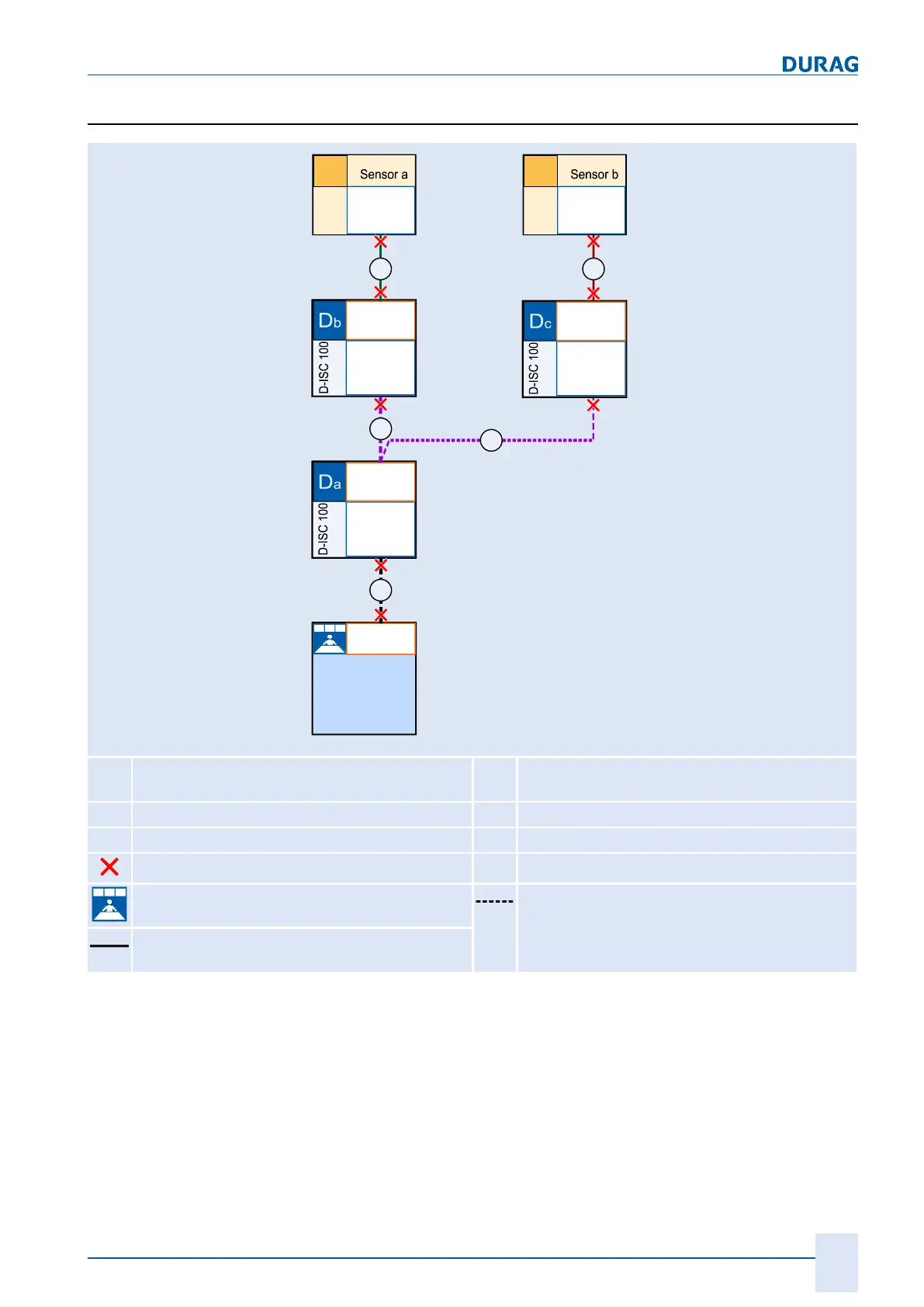
4.2.6 Sensor network bus architecture (multiple D-ISC 100)
Modbus
Master
PLC
P L Crogrammable ogic ontroller
D-EMS 2000
Environmental- and Process Data
Management System
D-ESI 100
D EURAG ngineering and
ervice nterfaceS I
Modbus
Master
Modbus
Slave
X2
Adr. v
X6
Modbus
Slave
Adr. y
Sa
B
Modbus
Master
Modbus
Slave
X2
Adr. w
X6
Modbus
Master
Modbus
Slave
X2
Adr. x
X6
A
B
C D
Modbus
Slave
Adr. z
Sb
D
x
D-ISC 100
A
Modbus A (Modbus RTU/TCP or
analogue/digital interfaces)
S
x
Sensor
B
Modbus B (Modbus RTU)
TB
Terminal box
C
Modbus C (Modbus RTU)
Bus termination
D
Modbus D (Modbus RTU)
Central monitoring room Bus cable
Pre-assembled
cable with connector (max. 12m)
Table4.3: Example system components and their bus connections
(multiple D‑ISC 100)
Overview of bus architecture
If more than one operation unit is required for a sensor, the bus
architecture specified above must be used. Up to two sensors
and three D‑ISC100s can be installed within this architecture.
Each of the two sensors can therefore be equipped with one on-
site operation unit (Db and Dc). (Da) acts as the central control
unit for the two sensors here, and as the interface to the evalu-
ation system. (Sb) and the associated (Dc) are optional; (Sb)
 Loading...